
Automatic stamping mechanism for stretching forming of cylindrical battery steel shell

A stretch forming, cylindrical battery technology, used in forming tools, feeding devices, manufacturing tools, etc., to avoid burns to workers, enhance air flow speed, and ensure accuracy

Active Publication Date: 2022-06-17
新乡市正元电子材料有限公司
View PDF9 Cites 2 Cited by
  • Summary
  • Abstract
  • Description
  • Claims
  • Application Information

AI Technical Summary

Problems solved by technology

[0004] In order to overcome the shortcomings of existing devices that still require workers to take out materials, the technical problem of the present invention is to provide an automatic stamping mechanism for cylindrical steel shell stretching and forming of cylindrical batteries that can automatically discharge materials

Method used


Image

  • Automatic stamping mechanism for stretching forming of cylindrical battery steel shell
  • Automatic stamping mechanism for stretching forming of cylindrical battery steel shell
  • Automatic stamping mechanism for stretching forming of cylindrical battery steel shell

Examples


Embodiment 1

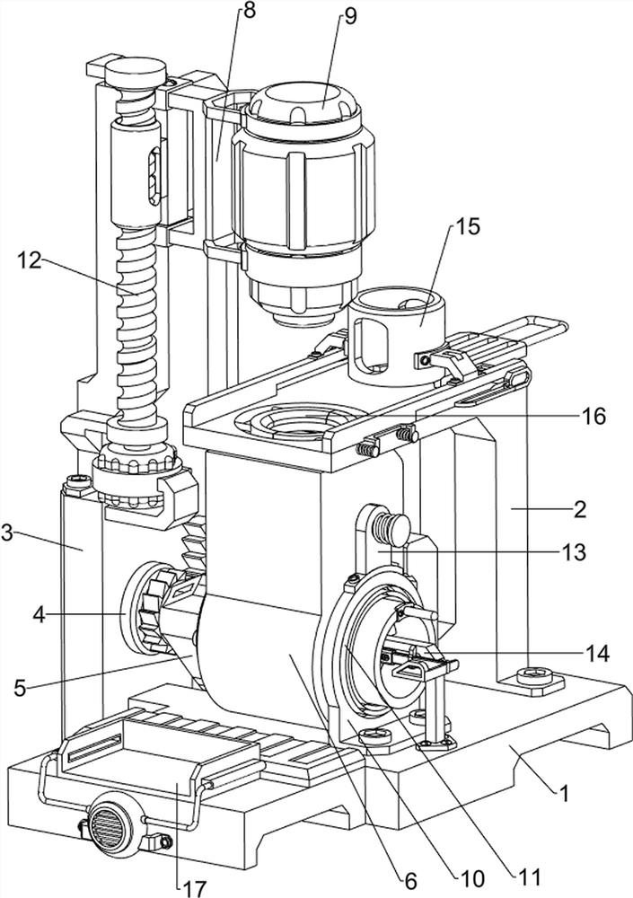
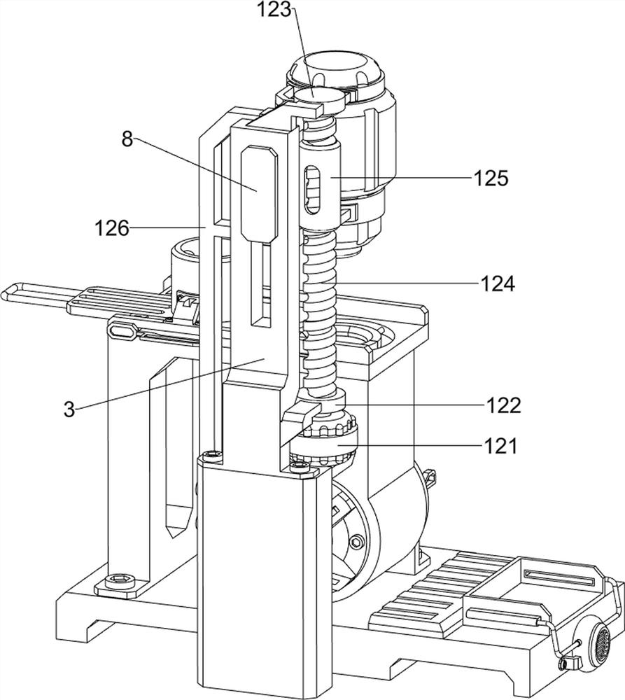
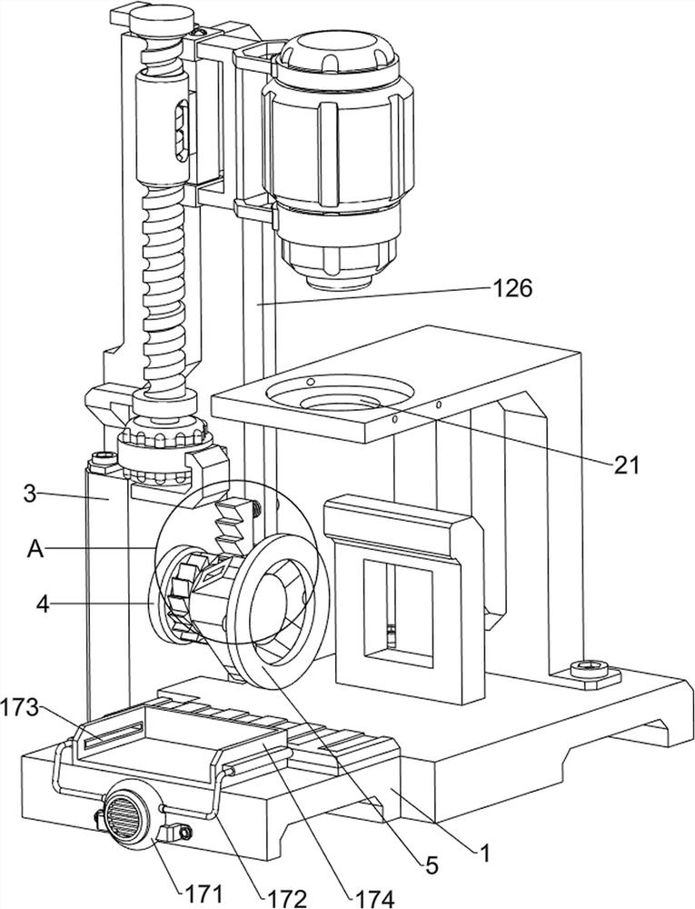
[0030] An automatic punching mechanism for drawing and forming a cylindrical battery steel shell, such as figure 1 , image 3 and Figure 7 As shown, it includes a base 1, a placing frame 2, a mounting plate 3, a bearing connecting seat 4, a connecting shaft frame 5, a die 6, a flat-top piston 7, a first connecting frame 8, a punching machine 9, a ring-type fixing frame 10, The return spring 11, the driving mechanism 12 and the ejecting mechanism 14 are connected with the placing frame 2 at the middle position of the top of the base 1, the left side of the placing frame 2 is provided with a feeding opening 21, and the rear side of the base 1 is connected with a mounting plate 3, and the mounting plate 3 The front side is connected with the bearing connecting seat 4, the bearing connecting seat 4 is rotatably connected with the connecting shaft frame 5, and the front side of the connecting shaft frame 5 is connected with a mold 6, which can assist the round steel sheet to be p...

Embodiment 2

[0035] On the basis of Example 1, as figure 1 , Figure 5 and Image 6 As shown, it also includes an anti-displacement mechanism 13, the anti-displacement mechanism 13 includes a mounting seat 131, a plug 132 and a second spring 133, the top of the ring-type fixing frame 10 is connected with a mounting seat 131, and the mounting seat 131 is slidably connected There is a pin 132, and a second spring 133 is connected between the pin 132 and the mounting seat 131. The second spring 133 plays a role in buffering and restoring the pin 132. A positioning groove 134 is opened on the upper side of the front part of the mold 6, and the pin 132 can be connected with the positioning groove. 134 is clamped and fixed, and the end of the plug 132 is designed with a round head, so that the plug 132 can be pushed and squeezed by the mold 6 .

[0036] When the mold 6 starts to turn counterclockwise, the mold 6 will squeeze the pin 132, so that the pin 132 slides forward, the pin 132 moves ou...


PUM


Abstract

The invention relates to an automatic stamping mechanism, in particular to an automatic stamping mechanism for stretching forming of a cylindrical battery steel shell. The invention provides the automatic stamping mechanism for stretching and forming the cylindrical steel shell of the cylindrical battery, which can automatically discharge. An automatic stamping mechanism for stretching forming of a cylindrical battery steel shell comprises a base, a containing frame, a mounting plate, a bearing connecting base, a connecting shaft frame, a die and the like, the containing frame is connected to the middle of the top of the base, the mounting plate is connected to the rear side of the base, the bearing connecting base is connected to the front side of the mounting plate, and the connecting shaft frame is rotationally connected to the bearing connecting base. The front side of the connecting shaft bracket is connected with a mold. The wedge-shaped block is extruded through the touch rod, so that the bevel baffle does not limit the round-head rod any more, the automatic discharging effect is achieved under pushing of the flat-top piston, the time for workers to take materials is effectively shortened, and the working efficiency is improved.

Description

technical field [0001] The invention relates to an automatic punching mechanism, in particular to an automatic punching mechanism for drawing and forming a cylindrical battery steel shell. Background technique [0002] A battery refers to a container that contains an electrolyte solution and a metal electrode to generate current. It is a device that can convert chemical energy into electrical energy. The battery has a relatively simple structure and is not affected by external climate and temperature. Its performance is stable and reliable. All aspects of life play a big role. In order to protect the internal components of the battery, the battery casing is usually a more sturdy cylindrical steel casing. [0003] Patent Publication No. CN210907723U describes a thin-walled battery shell drawing mold structure, including a base, a stamping plate and a steel shell, the top of the base is fixed with a lower mold by bolts, and the inside of the lower mold is respectively provided...

Claims


Application Information

Patent Timeline
Patent Type & Authority Applications(China)
IPC IPC(8): B21D22/20B21D37/16B21D43/00B21D43/20B21D45/02B21D43/24
CPCB21D22/20B21D37/16B21D43/003B21D43/20B21D45/02B21D43/24Y02E60/10
Inventor 韩昊梁平裴胜杰
Owner 新乡市正元电子材料有限公司
Learn More