Treatment gas suction structure and exhaust gas treatment device

An exhaust gas treatment device and gas treatment technology, which is applied in the direction of separation device, gas treatment, liquid variable capacity machinery, etc., can solve the problems of exhaust gas treatment device failure, low processing efficiency of gas treatment, etc., and achieve the effect of preventing products

Pending Publication Date: 2022-06-21
EBARA CORP
View PDF1 Cites 0 Cited by
  • Summary
  • Abstract
  • Description
  • Claims
  • Application Information

AI Technical Summary

Problems solved by technology

As a result, the exhaust gas treatment device may fail an

Method used


Image

  • Treatment gas suction structure and exhaust gas treatment device
  • Treatment gas suction structure and exhaust gas treatment device
  • Treatment gas suction structure and exhaust gas treatment device

Examples


Embodiment Construction

[0120] Hereinafter, embodiments of the present invention will be described with reference to the accompanying drawings. In the drawings described below, the same or equivalent structural elements are denoted by the same reference numerals, and overlapping descriptions are omitted. The exhaust gas treatment apparatus of the present embodiment is a wet exhaust gas treatment apparatus that detoxifies the treatment gas by contacting the treatment gas with a liquid, and can be used as one of manufacturing facilities for semiconductors, liquid crystals, solar panels, and LEDs, for example.

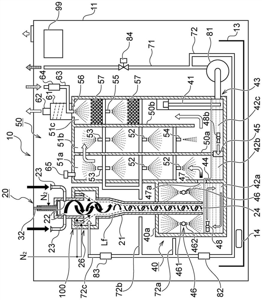
[0121] figure 1 It is a figure which shows one Embodiment of an exhaust gas processing apparatus. The exhaust gas treatment device 10 is installed to detoxify the gas (processing gas) from the vacuum pump. The primary side (upstream side) of the exhaust gas treatment device 10 is connected to a vacuum pump not shown. In addition, the exhaust gas treatment device of the present embodiment may ...


PUM


Abstract

The invention provides a processing gas suction structure and an exhaust gas treatment device which can prevent products from being generated from processing gas due to temperature reduction. A process gas suction structure (100) is provided with: a double-layer tube structure (101); and a heating device (102) for heating the double-layer pipe structure (101). A double pipe structure (101) is provided with: a process gas flow path part (105) through which a process gas flows; and a partition part (106) disposed on the outside of the process gas flow path part (105).

Description

technical field [0001] The present invention relates to a process gas suction structure and a waste gas treatment device. Background technique [0002] Vacuum pump devices are widely used as one of manufacturing equipments for semiconductors, liquid crystals, solar panels, LEDs, and the like. In these manufacturing processes and the like, a vacuum pump is connected to the vacuum chamber, and the processing gas introduced into the vacuum chamber is vacuum suctioned by the vacuum pump. [0003] The gas sucked by the vacuum pump may contain silane gas (SiH 4 ), dichlorosilane gas (SiH 2 Cl 2 ), ammonia (NH 3 ) and other harmful flammable gases, or NF 3 , ClF 3 , SF 6 , CHF 3 , C 2 F 6 , CF 4 and other halogen-based refractory gases. Therefore, such gas cannot be directly vented to the atmosphere. Conventionally, in a vacuum pump device, a detoxification device (an example of an exhaust gas treatment device) for detoxifying the gas sucked by the vacuum is provided i...

Claims


Application Information

Patent Timeline
IPC IPC(8): F04B37/14F04B39/06F04B39/12B01D47/06B01D53/68B01D53/70B01D53/78
CPCF04B37/14F04B39/06F04B39/123B01D53/78B01D53/68B01D53/70B01D47/06B01D2257/204B01D2257/2066B01D2257/553B01D2257/406B01D2258/0216B01D53/75B01D47/02B01D2247/04B01D47/10B01D47/063B01D47/022B01D2258/01B01D53/79
Inventor 关根贵史宫崎一知
Owner EBARA CORP
Why Eureka
Try Eureka