Long-acting heating hot compress patch structure

A hot compress, long-acting technology, applied in the direction of heating appliances for treatment, cooling appliances for treatment, contraceptives, etc., can solve limited problems, the longest is no more than 10-20 minutes, the heating performance of the heating patch is weak, There are no problems such as long-term hot compress, and the effect of ensuring hot compress effect, increasing the area of ​​action and good effect is achieved.

Pending Publication Date: 2022-06-24
左点健康产业(深圳)有限公司
View PDF0 Cites 0 Cited by
  • Summary
  • Abstract
  • Description
  • Claims
  • Application Information

AI Technical Summary

Problems solved by technology

[0003] The structure of the traditional heating patch consists of a heating layer, a drug layer, and a release film bonded to the two. The release film can be attached to the affected area after the release film is removed. Finally, the heating material will be in contact with a large amount of air, which makes the heating material react quickly, and the duration of the heating effect is very limited, the longest is only 10-20 minutes, which is far from achieving the purpose of long-term hot compress, and as the reaction progresses , the heating material on the front side will be consumed quickly, which makes the heating performance of the second half of the heating patch weak. A long-term heating heating patch structure is specially provided to solve the above problems

Method used


Image

  • Long-acting heating hot compress patch structure
  • Long-acting heating hot compress patch structure
  • Long-acting heating hot compress patch structure

Examples


Embodiment 1

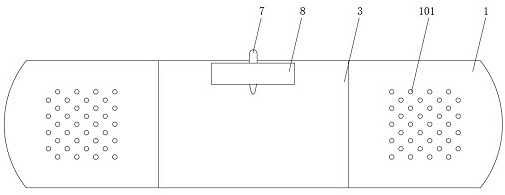
[0025] Example 1, as Figure 1-Figure 2 As shown, a long-lasting heat-generating thermal compress structure according to the present invention includes an adhesive film 1, a release film 2 and a hot compress bag 3, and a release film 2 is adhered to the lower edge of the adhesive film 1, A heat compress bag 3 is arranged in the middle of the adhesive film 1, wherein the heat compress bag 3 is provided with a first reactant space 4, a second reactant space 5 and a medicine storage space 6 which are independent of each other. The reactant space 4 and the second reactant space 5 are filled with exothermic materials, the medicine placement space 6 is filled with applied medicine, and the first reactant space 4 and the second reactant space 5 can communicate with each other. , the drug placement space 6 is arranged on the side close to the release film 2, so that the reaction heat after the reactants in the first reactant space 4 and the second reactant space 5 are mixed with each ...

Embodiment 2

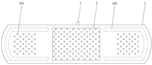
[0033] Example 2, as Figure 1-Figure 4As shown, a long-lasting heat-generating thermal compress structure according to the present invention includes an adhesive film 1, a release film 2 and a hot compress bag 3, and a release film 2 is adhered to the lower edge of the adhesive film 1, A heat compress bag 3 is arranged in the middle of the adhesive film 1, wherein the heat compress bag 3 is provided with a first reactant space 4, a second reactant space 5 and a medicine storage space 6 which are independent of each other. The reactant space 4 and the second reactant space 5 are filled with exothermic materials, the medicine placement space 6 is filled with applied medicine, and the first reactant space 4 and the second reactant space 5 can communicate with each other. , the drug placement space 6 is arranged on the side close to the release film 2, so that the reaction heat after the reactants in the first reactant space 4 and the second reactant space 5 are mixed with each o...

Embodiment 3

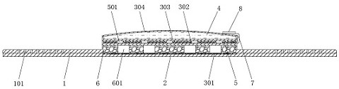
[0042] Example 3, as figure 1 , figure 2 , Figure 5 As shown, a long-lasting heat-generating thermal compress structure according to the present invention includes an adhesive film 1, a release film 2 and a hot compress bag 3, and a release film 2 is adhered to the lower edge of the adhesive film 1, A heat compress bag 3 is arranged in the middle of the adhesive film 1, wherein the heat compress bag 3 is provided with a first reactant space 4, a second reactant space 5 and a medicine storage space 6 which are independent of each other. The reactant space 4 is divided into two storage cavities 9. The liquid heating material and the gaseous pressurized material are respectively stored in the two storage cavities 9, and the two storage cavities 9 are arranged in layers. The medicine space 6 is filled with applied medicine, and the liquid storage cavity 9 in the first reactant space 4 can communicate with the second reactant space 5. The medicine storage space 6 is set close t...


PUM


Abstract

The invention relates to the technical field of medical care, in particular to a long-acting heating hot compress patch structure which comprises an adhesive film, a release film and a hot compress bag, the release film is adhered to the edge of the lower side of the adhesive film, and the hot compress bag is arranged in the middle of the adhesive film. A first reactant space, a second reactant space and a medicine containing space which are independent of one another are arranged in the hot compress bag, the first reactant space is divided into two storage cavities, a liquid heating material and a gaseous pressurizing material are stored in the two storage cavities respectively, the two storage cavities are arranged in a layered mode, and the liquid heating material and the gaseous pressurizing material are arranged in the medicine containing space. According to the long-acting heating hot compress paste structure, the heating raw materials can be stored in the first reactant space and the second reactant space respectively, the heating process is completely controllable, due to the fact that the heating process does not need to act with external air, the effect of the heating raw materials on the external air is not needed, and the long-acting heating effect is achieved. And the purity of reactants is higher.

Description

technical field [0001] The invention relates to the technical field of medical care, in particular to a heat compress structure for long-term heating. Background technique [0002] Fever patch is a kind of medicine, the main effect is used for frozen shoulder, cervical spondylosis, bone hyperplasia, lumbar disc herniation, rheumatoid arthritis, bruises, waist and leg pain, etc. The raw material layer, the gelatin layer and the non-woven bag are composed of four parts. The raw material layer is placed in the non-woven bag. The gelatin layer is used to make a sticker adhere to the clothes. The raw material layer is made of iron, stone, activated carbon, inorganic Synthetic polymers such as salt and water can undergo an exothermic reaction under the action of oxygen in the air. The characteristics of the non-woven bag are uniform, leak-proof and good air permeability. The gelatin layer is made of Japan's unique high-quality pressure-sensitive adhesive coating. It is firmly bon...

Claims


Application Information

Patent Timeline
Patent Type & Authority Applications(China)
IPC IPC(8): A61F7/02A61F7/03
CPCA61F7/02A61F7/03A61F2007/0204A61F2007/022A61F2007/0226A61F2007/0228A61F2007/0244A61F2007/0257A61F2007/0258A61F2007/0261
Inventor 朱江涛向文林许立陈可夫向文明
Owner 左点健康产业(深圳)有限公司
Why Eureka
Try Eureka