Device and method for preparing gas-based shaft furnace reducing gas by purifying biomass gas

A gas-based shaft furnace and biomass gas technology, applied in chemical instruments and methods, shaft furnaces, furnaces, etc., can solve the problems of high production cost, waste of heat, air pollution, etc., to improve active ingredients, avoid air pollution, The effect of high heat exchange efficiency

Active Publication Date: 2022-06-24
HEILONGJIANG JIANLONG IRON & STEEL
View PDF9 Cites 0 Cited by
  • Summary
  • Abstract
  • Description
  • Claims
  • Application Information

AI Technical Summary

Problems solved by technology

[0008] The purpose of the present invention is to solve the problem that existing tubular heating furnaces prepare reducing gas systems that have high preparation costs and generate CO emissions. 2 and other exhaust gases, causing heat waste and air pollution problems

Method used


Image

  • Device and method for preparing gas-based shaft furnace reducing gas by purifying biomass gas
  • Device and method for preparing gas-based shaft furnace reducing gas by purifying biomass gas
  • Device and method for preparing gas-based shaft furnace reducing gas by purifying biomass gas

Examples


specific Embodiment approach 1

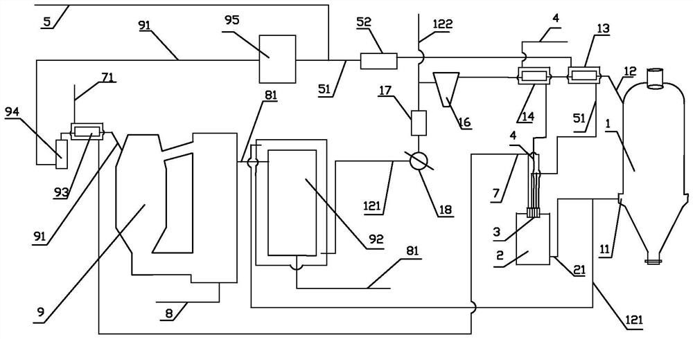
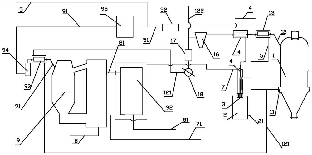
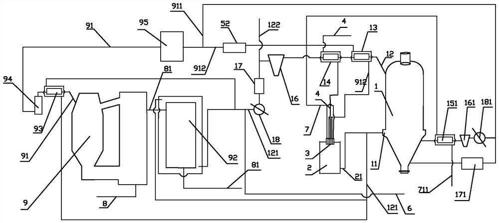
[0035] Embodiment 1: Combining figure 1 , figure 2 , Figure 4 to Figure 6 Illustrating this embodiment, this embodiment includes a gas-based shaft furnace 1, a gas-based shaft furnace top purification gas heating device, a biomass generator 9, a biomass gas ammonia water cooler 94, a biomass gas purification system 95, and a non-catalytic part Oxidation reformer 2, gas compressor 52, gas-based shaft furnace top hot gas heat exchanger 1 13, gas-based shaft furnace top gas dust collector 16, gas-based shaft furnace top gas de-CO 2 components, hydrocarbon-rich gas source 5, pure oxygen source 4 and water vapor source 7;

[0036] The biomass generator 9 is sequentially communicated with the biomass gas ammonia water cooler 94 and the biomass gas purification system 95 through the ascending pipeline, and the biomass gas 91 generated in the biomass generator 9 flows through the biomass gas ammonia water cooler 94 and the biomass gas. The biomass gas purification system 95, the ...

specific Embodiment approach 2

[0037] Specific implementation mode 2: Combining figure 1 , figure 2 , Figure 4 to Figure 6 Illustrating this embodiment, between the gas-based shaft furnace top hot gas heat exchanger 13 and the gas-based shaft furnace top gas dust collector 16 in this embodiment are also sequentially connected to the shaft furnace hot gas heat exchanger 2 14 and the shaft furnace. Hot gas heat exchanger three 15. Other components and connection relationships are the same as in the first embodiment.

specific Embodiment approach 3

[0038] Specific implementation three: combination figure 1 , figure 2 , Figure 4 to Figure 6 Illustrating this embodiment, the gas-based shaft furnace top purification gas heating device in this embodiment is the biomass gas generator hot flue gas heat exchanger 92 and / or the biomass gas riser heat exchanger 93; the biomass generator 9 A biomass gas riser heat exchanger 93 is installed outside the riser pipe between the biomass gas ammonia water cooler 94, and a biomass generator hot flue gas heat exchanger 92 is installed outside the hot flue gas pipeline 81 of the biomass generator. . This arrangement facilitates selection of at least one heat exchange mode according to different operating conditions. Other compositions and connection relationships are the same as in the first or second embodiment.


PUM


Abstract

The invention discloses a device and a method for preparing gas-based shaft furnace reducing gas by purifying biomass gas, and relates to a device for preparing the gas-based shaft furnace reducing gas. The invention aims to solve the problems of heat waste and air pollution caused by high preparation cost and generation of discharged CO2 and other waste gases in the existing system for preparing the reducing gas by the tubular heating furnace. Raw material gas containing biomass gas is introduced into a gas heating furnace through a pipeline to be heated; gas in the gas heating furnace is reformed into first reducing gas, the first reducing gas enters the gas-based shaft furnace, iron oxide reacts with the reducing gas in the gas-based shaft furnace and is directly reduced into reduced iron, the directly reduced iron is discharged out of the furnace through the lower part of the gas-based shaft furnace, raw gas generated by the reaction is discharged from the top of the shaft furnace, and second reducing gas is added into the first reducing gas; and after the temperature is adjusted, the gas enters the gas-based shaft furnace. The problems of external combustion heating and smoke emission of the tubular heating furnace are solved, intermediate medium heat exchange is not needed, and the heat exchange efficiency is high. The method is used for preparing the reduced iron.

Description

technical field [0001] The invention relates to a device and method for preparing gas-based shaft furnace reducing gas, in particular to a device for preparing gas-based shaft furnace reducing gas by using purified biomass gas. Background technique [0002] The gas-based shaft furnace process is a clean iron-making technology and an important technical means for my country's iron and steel industry to achieve the dual-carbon goal. However, in the prior art, the main gas source for gas-based shaft furnaces is natural gas, and the current situation of resources in my country is that there is more coal and less gas. become increasingly important. To this end, domestic and foreign technicians have studied the gas-based shaft furnace technology of non-natural gas sources, and the research direction is coal-to-gas technology. Coal is a non-renewable resource, and its development prospects are limited. [0003] In addition, the existing gas-based shaft furnace process uses a tubul...

Claims


Application Information

Patent Timeline
Patent Type & Authority Applications(China)
IPC IPC(8): C21B13/02C01B3/02C01B3/34C01B3/50C01B3/52
CPCC21B13/0073C21B13/02C01B3/02C01B3/34C01B3/50C01B3/52
Inventor 张春雷王忠英李海涛王前金守成王启丞
Owner HEILONGJIANG JIANLONG IRON & STEEL
Why Eureka
Try Eureka