Eureka AIR delivers breakthrough ideas for toughest innovation challenges, trusted by R&D personnel around the world.

Temporary concrete road reinforcing device for soft soil layer construction

A technology for concrete roads and reinforcement devices, which is applied in the direction of support devices, earthwork drilling, soil protection, etc., and can solve problems such as deformation, increased road construction costs, and long time required for plastic drainage board methods

Pending Publication Date: 2022-06-24
ZHEJIANG XINSHENG CONSTR GROUP
View PDF0 Cites 0 Cited by
  • Summary
  • Abstract
  • Description
  • Claims
  • Application Information

AI Technical Summary

Problems solved by technology

With the rapid development of our country's national economy and the vigorous rise of our country's basic construction, the construction land is becoming increasingly scarce. Many projects have to be built on sites that were considered unsuitable for construction in the past, and buildings (structures) are built on weak soil layers. When the natural foundation is used, its strength often cannot meet the design requirements, and a series of problems such as soil stability and deformation are encountered.
[0003] In the early stage of construction, some construction sites need to build temporary roads in order to facilitate the transportation of building materials; however, when building roads on the surface of weak foundations, the weak foundations need to be reinforced; in the process of strengthening deep weak foundations, workers often use sand cushions However, the sand cushion method and the plastic drainage board method take a long time, but the construction period for laying temporary roads is tight, so it is not suitable to use this method to strengthen the foundation; use pile extrusion The dense reinforcement method is too expensive for foundation reinforcement, which increases the cost of road construction

Method used


Image

  • Temporary concrete road reinforcing device for soft soil layer construction
  • Temporary concrete road reinforcing device for soft soil layer construction
  • Temporary concrete road reinforcing device for soft soil layer construction

Examples


Embodiment Construction

[0025] The present invention will be further described below with reference to the accompanying drawings and embodiments.

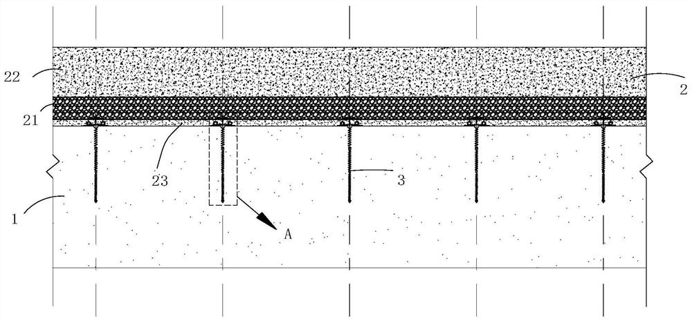
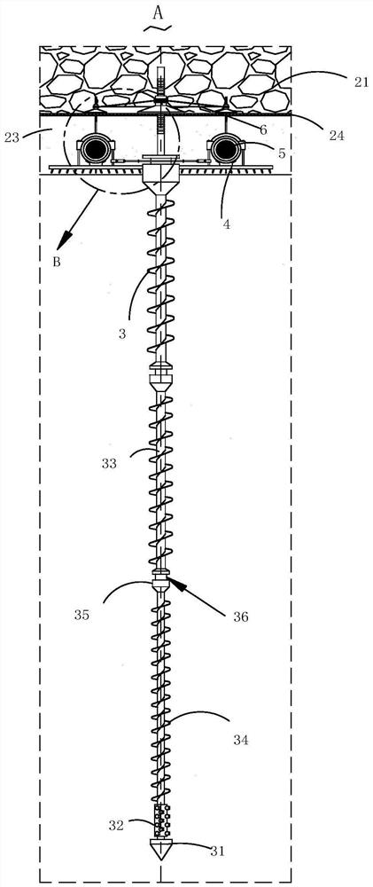
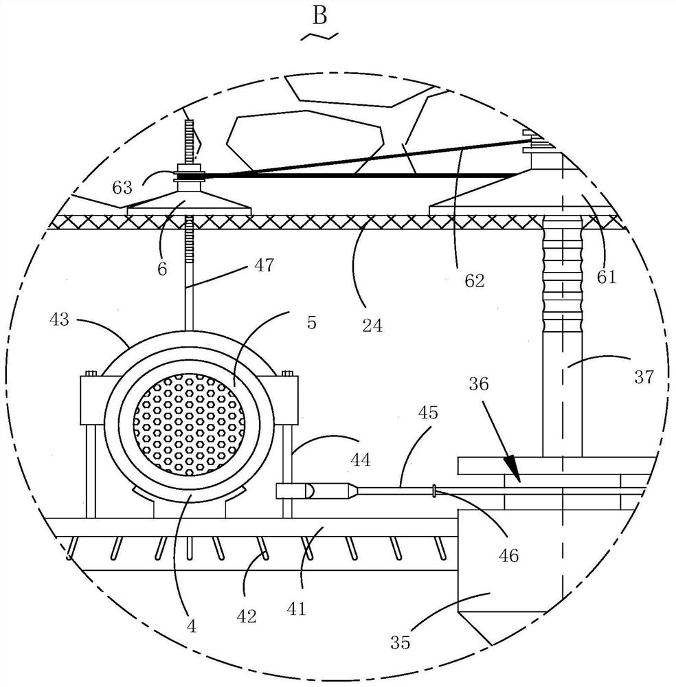
[0026] Please refer to figure 1 , figure 2 , image 3 , Figure 4 , Figure 5 , Image 6 , Figure 7 , Figure 8 and Figure 9 ,in, figure 1 The structural schematic diagram of the temporary concrete road reinforcement device for soft soil layer construction provided by the present invention; figure 2 for figure 1 Shown is the enlarged schematic diagram of the structure at A; image 3 for figure 2 The enlarged schematic diagram of the structure at B shown; Figure 4 for image 3 The top view of the wire mesh structure shown; Figure 5 for image 3 The schematic diagram of the internal structure of the fixing pad shown; Image 6 for image 3 The top view of the fixing plate structure shown; Figure 7 for Image 6 Side view of the internal structure of the drain pipe shown; Figure 8 for figure 1 The schematic diagram of the grouting m...


PUM


Abstract

The invention provides a temporary concrete road reinforcing device for soft soil layer construction. The temporary concrete road reinforcing device for soft soil layer construction comprises a soft soil layer. The inner wall of the soft soil layer is rotationally connected with the three drill rods, the spiral blades are installed on the side walls of the drill rods, and the drill bit and the spray head are installed at the bottom end of the drill rod located on the lowest portion; a fixing mechanism; a support mechanism; a drainage mechanism; the reinforcing mechanism comprises a fixing pad, a second steel wire, a connecting sleeve and an inclined rod, the connector and the top end of the supporting mechanism are connected with the fixing pad in a sliding mode, the connecting sleeve is installed on the side wall of the fixing pad, and the side wall of the connecting sleeve is sleeved with the second steel wire; the multiple inclined rods are obliquely mounted in the fixing pad, and the steel wire mesh is clamped by the inclined rods; a fixing mechanism; the temporary concrete road reinforcing device for soft soil layer construction has the advantages of being capable of rapidly reinforcing a foundation and low in manufacturing cost.

Description

technical field [0001] The invention relates to the technical field of soft soil layer reinforcement, in particular to a temporary concrete road reinforcement device for soft soil layer construction. Background technique [0002] Soft soil generally refers to soft soil with loose soil, high compressibility and low shear strength and untreated fill. A foundation whose bearing layer is mainly composed of soft soil is called a soft foundation. With the rapid development of my country's national economy and the vigorous rise of my country's capital construction, the construction land is increasingly tight, and many projects have to be built on sites that were considered unsuitable for construction needs in the past, and buildings (structures) are built on weak soil layers. When the natural foundation is used, its strength often cannot meet the design requirements, and a series of problems such as soil stability and deformation are encountered. [0003] In the early stage of con...

Claims


Application Information

Patent Timeline
Patent Type & Authority Applications(China)
IPC IPC(8): E02D3/00E02D3/10E02D3/12E21B7/04E21B15/04E21B17/04E21B17/22E21B33/138
CPCE02D3/00E02D3/10E02D3/12E21B7/04E21B15/04E21B17/04E21B17/22E21B33/138
Inventor 赵国民庄宁张亚运齐佳陈鹏娄力栋施如霞张敬普
Owner ZHEJIANG XINSHENG CONSTR GROUP
Why Eureka
Eureka Blog
Learn More