
Manufacturing method of semiconductor device

A manufacturing method and semiconductor technology, applied in semiconductor/solid-state device manufacturing, semiconductor devices, manufacturing tools, etc., can solve the problems of grinding uniformity, device electrical performance degradation, and long verification cycle, etc., to achieve high cleanliness and High-quality film quality, reduce the cost of grinding process, and realize the effect of film quality

Pending Publication Date: 2022-06-24
CSMC TECH FAB2 CO LTD
View PDF0 Cites 0 Cited by
  • Summary
  • Abstract
  • Description
  • Claims
  • Application Information

AI Technical Summary

Problems solved by technology

The above technical solutions optimized from the perspective of hardware, consumables and single factors have their own characteristics, but they all introduce new conditions and factors into the CMP process system, and have disadvantages such as high implementation costs and long verification cycles.
At the same time, these methods of improving the planarization of trench isolation structures rely more on advanced hardware equipment and consumables, which can improve the uniformity problem to a certain extent, but for devices with more advanced technology nodes and special structures, a single improvement does not Can not completely solve the problem of grinding uniformity
If during the STI CMP grinding process, if the residual film thickness and shape cannot be well controlled in the early stage, the difference in the film thickness step shape of the front layer will be further amplified, resulting in over-grinding of silicon oxide in the groove and dishing in the center of the wafer surface. Chromatic aberration (discolor) occurs at the edge, resulting in a decrease in the electrical performance of the device and a decrease in yield

Method used


Image

  • Manufacturing method of semiconductor device
  • Manufacturing method of semiconductor device
  • Manufacturing method of semiconductor device

Examples


Embodiment Construction

[0036] In the following description, numerous specific details are set forth in order to provide a more thorough understanding of the present invention. It will be apparent, however, to one skilled in the art that the present invention may be practiced without one or more of these details. In other instances, some technical features known in the art have not been described in order to avoid obscuring the present invention.

[0037] For a thorough understanding of the present invention, a detailed description will be set forth in the following description to explain the method of fabricating the semiconductor device of the present invention. Obviously, the practice of the present invention is not limited to the specific details familiar to those skilled in the semiconductor arts. Preferred embodiments of the present invention are described in detail below, however, the present invention may have other embodiments in addition to these detailed descriptions.

[0038] It should ...


PUM


Abstract

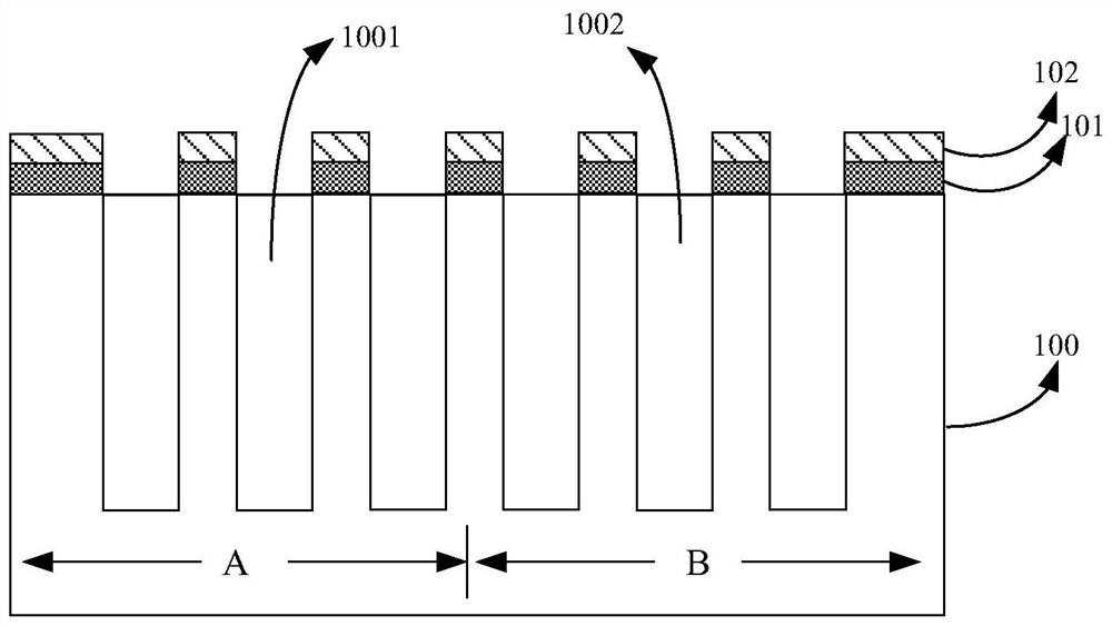
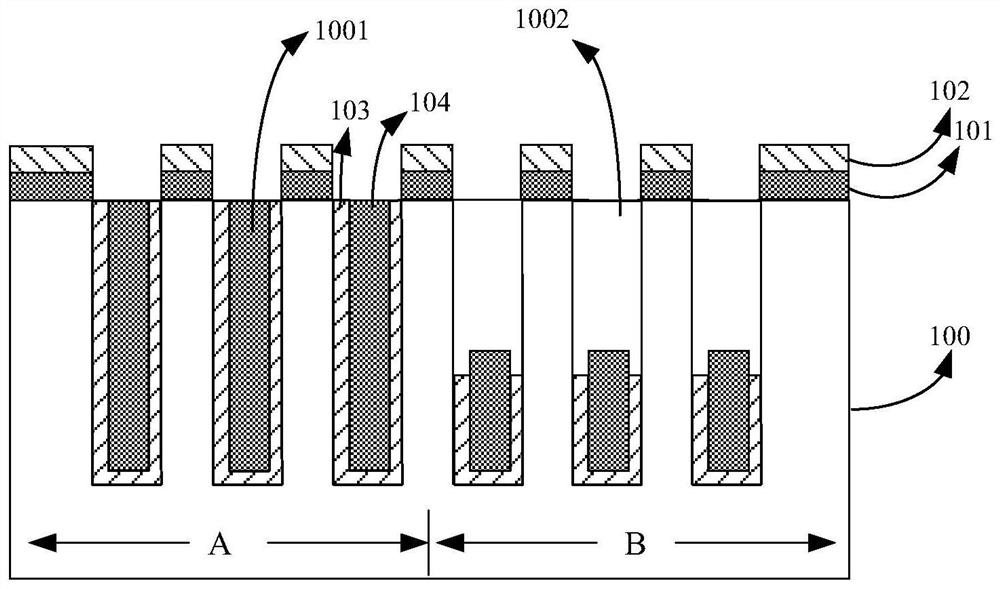
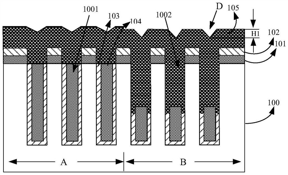
The invention discloses a manufacturing method of a semiconductor device. The method comprises the following steps: S1, providing a semiconductor substrate, forming a grinding barrier layer on the surface of the semiconductor substrate, forming a groove in the semiconductor substrate, and filling the groove with first filling layers with different thicknesses to obtain a first groove and a second groove with different depth ratios; s2, executing a deposition process to form an isolation material layer, wherein the isolation material layer covers the surface of the semiconductor substrate and fills the second groove with the remaining depth; and S3, executing a first chemical mechanical polishing process to remove the isolation material layer on the surface of the semiconductor substrate. According to the invention, according to the step difference formed after filling of the grooves with different depth-to-width ratios, the distribution of the grinding liquid on the grinding pad is adjusted by adjusting the drop point position of the grinding liquid supplied to the grinding pad, so that the high-smoothness and high-uniformity film layer quality is realized, and meanwhile, the grinding process cost is greatly reduced.

Description

technical field [0001] The present invention relates to the technical field of semiconductors, and in particular, to a method for manufacturing a semiconductor device. Background technique [0002] As the size of integrated circuit devices gradually shrinks, advanced processes (below 0.13um) usually use trench isolation (STI) technology to improve device density and isolation. In order to achieve the ideal isolation effect, the aspect ratio (AR) of the trench isolation structure increases as the technology node continues to shrink. However, after HDP-CVD filling of trenches with high aspect ratios, the difference in silicon oxide thickness between the trench isolation region and the non-trench isolation region (active region or active region) will gradually increase, and the die will gradually increase. (cell) density / ISO area trench and silicon oxide thickness step difference on the active area will be further magnified. At the same time, in the design of deep trench stru...

Claims


Application Information

Patent Timeline
Patent Type & Authority Applications(China)
IPC IPC(8): H01L21/3105H01L21/28B24B57/02B24B37/04
CPCH01L21/31051H01L21/28158B24B37/042B24B57/02
Inventor 贺腾飞
Owner CSMC TECH FAB2 CO LTD
Learn More