
Method for increasing permeability of cytoplasmic membrane and structure suitable for same

A cytoplasmic membrane and structure technology, applied in the field of increasing the permeability of cytoplasmic membrane, can solve problems such as limiting molecular efficiency, and achieve the effect of avoiding fragmentation or release

Pending Publication Date: 2022-06-24
TRINCE BV
View PDF3 Cites 0 Cited by
  • Summary
  • Abstract
  • Description
  • Claims
  • Application Information

AI Technical Summary

Problems solved by technology

The disadvantage of this approach is that the cell membrane is permeabilized on one side (i.e., the side where the cell is in contact with the substrate surface structure (bottom side of the cell)), but the compound that needs to be delivered into the cell is mainly present on the other side (cell side). upper side of
This limits the efficiency with which molecules, especially large molecules, can enter cells

Method used


Image

  • Method for increasing permeability of cytoplasmic membrane and structure suitable for same
  • Method for increasing permeability of cytoplasmic membrane and structure suitable for same
  • Method for increasing permeability of cytoplasmic membrane and structure suitable for same

Examples


Embodiment 1

[0141] Example 1 Porous structure comprising nanofiber web and particles embedded in nanofibers

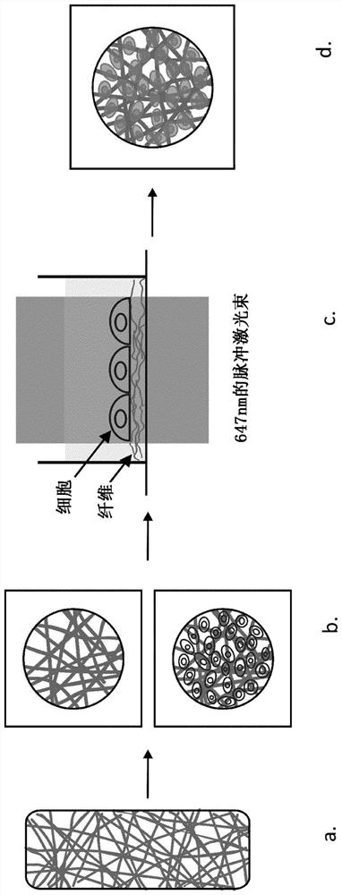
[0142] A second embodiment of the structure of the present invention includes a porous structure comprising nanofibers and particles capable of absorbing electromagnetic radiation embedded in the nanofibers. The examples described below include polycaprolactone as a structural material and iron oxide nanopowders as particles capable of absorbing electromagnetic radiation. Obviously, other materials and other particles are also contemplated.

[0143] 1.a Synthesis and characterization of photothermal electrospun nanofibers

[0144] The following materials were used to synthesize nanofiber webs:

[0145] Polycaprolactone (PCL, Mw≈70,000g / mol);

[0146] ·N,N-Dimethylformamide (DMF);

[0147] Tetrahydrofuran (THF);

[0148] Iron oxides (Fe 3 O 4 ) Nanopowder (IONP) (#MKBW3262, Sigma-Aldrich, Belgium);

[0149] Poly(allylamine hydrochloride) (PAH, Mw=17,560 g / mol, #MKBZ2824V, S...

Embodiment 2

[0203] Example 2 Non-porous structure comprising polymeric material and nanoparticles

[0204] Figure 21a A schematic diagram of an embodiment of the structure 1 of the present invention is shown. Figure 21b shown Figure 21a Structure 1 is shown in cross section along line AA'. The structure 1 comprises a polymer sheet comprising a polymer material 2 and particles 3 capable of absorbing electromagnetic radiation. The particles 3 include, for example, carbon particles or iron oxide particles or a combination of carbon particles and iron oxide particles. The particles 3 are embedded in the material 2 and have an average equivalent spherical diameter d of, for example, 1000 nm.

[0205] The structure has a thickness t of 0.1 μm to 100 μm, for example a thickness of 1 μm, 2 μm or 5 μm.

[0206] The ratio of the free area surface S of the structure to the volume V of the structure, ie the ratio S / V, is 1 / t.

[0207] The polymer sheet preferably comprises a polymer comprisi...


PUM

PropertyMeasurementUnit
diameteraaaaaaaaaa
thicknessaaaaaaaaaa
diameteraaaaaaaaaa

Abstract

The present invention relates to a method for increasing the permeability of a cytoplasmic membrane by directing at least one cell onto or near a structure comprising particles capable of absorbing electromagnetic radiation. The particles are present at a concentration of 0.001 to 20 vol% and are embedded in the material of the structure. At least 60% of the particles present in the structure are embedded in the material such that the shortest distance L between these particles and the free region surface S of the structure is 1 nm to 500 nm. The invention also relates to a structure suitable for the permeabilization of cells in photo-thermal processes and to the use of said structure.

Description

technical field [0001] The present invention relates to a method of increasing the permeability of the cytoplasmic membrane by directing cells onto or near a structure comprising embedded particles and irradiating the structure. The methods of the present invention do not require contact between particles and cells. The present invention also relates to a structure suitable for use in a method for increasing the permeability of the cytoplasmic membrane. Background technique [0002] Intracellular delivery of exogenous compounds in cells is a common requirement in many biotechnological and biomedical applications. Examples are the creation of mutant cell lines for basic research, drug screening of biopharmaceutical compounds, and the production of cells (eg, CAR-T cells) for cell-based immunotherapy. Regardless of the specific application, the common challenge is to overcome the cell membrane, which is a major hurdle, especially for macromolecules like DNA, RNA or proteins....

Claims


Application Information

Patent Timeline
Patent Type & Authority Applications(China)
IPC IPC(8): C12M1/42
CPCC12M35/02
Inventor K·布雷克曼斯熊然华S·德斯美特
Owner TRINCE BV
Learn More