
Manufacturing method for forming multiple parts with threaded holes in batches

A manufacturing method, technology of threaded hole

Active Publication Date: 2022-06-28
AVIC BEIJING AERONAUTICAL MFG TECH RES INST
View PDF7 Cites 0 Cited by
  • Summary
  • Abstract
  • Description
  • Claims
  • Application Information

AI Technical Summary

Problems solved by technology

[0002] Parts with threaded holes serving in marine or other corrosive environments cannot be protected against corrosion by painting or coating due to their combined use. Corrosion is prone to occur at the hole position, which affects the use. Since this part is used in a large number, once it needs to be replaced, it needs to be replaced with a new part. In fact, the only part that is corroded is the hole structure position, so replacing all parts will cause waste of parts , and will greatly increase the replacement cost, and the part with the threaded hole needs to be threaded with other parts, and the parent material cannot be replaced
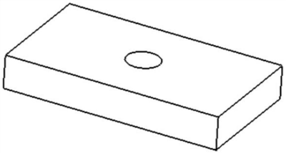
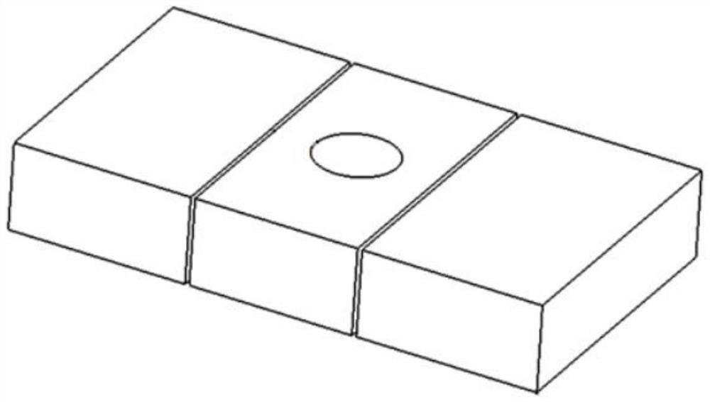
[0003]The current structure of this type of parts, such as Figure 1, it is made of high-strength steel alloy material as a whole, and the threaded hole is not resistant to corrosion, which may easily lead to structural failure. Therefore, it is proposed to divide the structural hole and replace the material. Split the entire part with holes or hollow out the holes and surrounding areas, such as As shown in Figure 2, replace the material of the disassembled hole with a corrosion-resistant material, such as a corrosion-resistant stainless steel material, so that the hole structure is located on the stainless steel material, and then weld and glue Or mechanical connection to achieve connection with other parts, but the use of ordinary fusion welding requires opening grooves for multiple welding, the performance of the wide heat-affected zone is not good, the use of glue joints will make the connection strength lower, and the use of expansion and tightening structures will form gaps And only one part can be manufactured at a time

Method used


Image

  • Manufacturing method for forming multiple parts with threaded holes in batches
  • Manufacturing method for forming multiple parts with threaded holes in batches
  • Manufacturing method for forming multiple parts with threaded holes in batches

Examples


Embodiment Construction

[0031] The embodiments of the present invention will be described in further detail below with reference to the accompanying drawings and examples. The detailed description of the following embodiments and the accompanying drawings are used to exemplify the principles of the present invention, but not to limit the scope of the present invention, that is, the present invention is not limited to the described embodiments without departing from the spirit of the present invention. Any modifications, substitutions and improvements to parts, assemblies and connections are covered under.

[0032] It should be noted that the embodiments in the present application and the features of the embodiments may be combined with each other in the case of no conflict. The present application will be described in detail below with reference to the accompanying drawings and in conjunction with the embodiments.

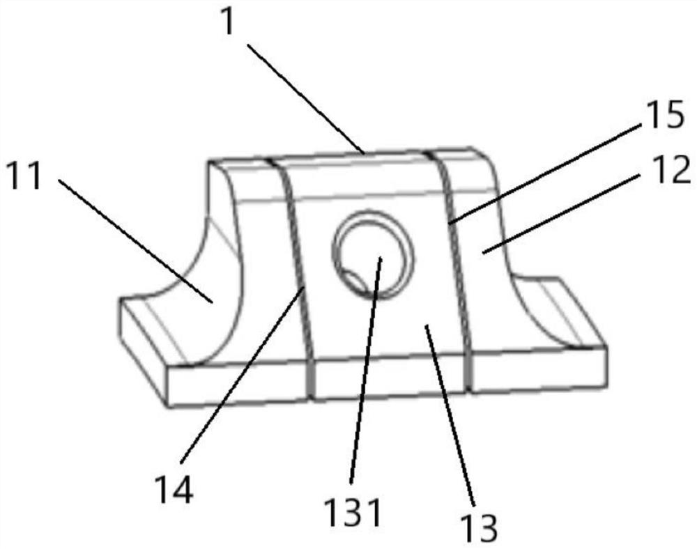
[0033] like Figure 3-Figure 7 As shown, the present invention provides a manufactu...


PUM

PropertyMeasurementUnit
lengthaaaaaaaaaa

Abstract

The invention relates to a manufacturing method for forming a plurality of parts with threaded holes in batches, which comprises the following steps: selecting a plurality of blank workpieces, preparing a first blank workpiece and a second blank workpiece by adopting a high-strength steel alloy material, preparing a third blank workpiece by adopting a corrosion-resistant stainless steel material, the three blank workpieces are connected into a complete structure body through the linear friction welding technology, and a first welding seam and a second welding seam are formed in the complete structure body; performing heat treatment on the complete structure body; and by taking the first welding seam or the second welding seam on the complete structural body as a benchmark, machining the complete structural body by adopting a machining mode according to the appearance structure of the part, and forming the threaded holes in the third blank to obtain a plurality of parts with the threaded holes. The threaded hole is formed in the corrosion-resistant stainless steel material and matched with the high-strength steel alloy material, integrated manufacturing is achieved through the linear friction welding technology, and the corrosion resistance of the part with the threaded hole in the corrosion environment for a long time is improved.

Description

technical field [0001] The invention relates to the technical field of welding and manufacturing, in particular to a manufacturing method for batch molding a plurality of parts with threaded holes. Background technique [0002] Parts with threaded holes that serve in marine or other corrosive environments cannot be protected against corrosion by painting or coating due to their combined use. During use, rust is likely to occur at the position of the hole, which affects the use. Due to the number of parts used There are many parts, once they need to be replaced, they need to be replaced with new parts. In fact, the parts that are corroded are only the hole structure positions. Therefore, all replacements will cause waste of parts, and will greatly increase the replacement cost, and the parts with threaded holes Requires a threaded connection with other parts and cannot replace the parent material [0003] The current structure of such parts, such as figure 1 As shown, the h...

Claims


Application Information

Patent Timeline
Patent Type & Authority Applications(China)
IPC IPC(8): B23P15/00
CPCB23P15/00
Inventor 季亚娟陶军张传臣佀好学李菊
Owner AVIC BEIJING AERONAUTICAL MFG TECH RES INST
Learn More