Prestressed post-inserted composite anchor cable uplift pile and on-site loading equipment thereof

A technology of prestressed and pull-resistant piles, which is applied in the test of sheet pile walls, buildings, and foundation structures, etc., to achieve the effects of reducing inclination and position deviation, eliminating tensile stress, and high corrosion resistance

Pending Publication Date: 2022-06-28
CHINA ACAD OF BUILDING RES +1
View PDF1 Cites 0 Cited by
  • Summary
  • Abstract
  • Description
  • Claims
  • Application Information

AI Technical Summary

Problems solved by technology

[0005] The purpose of the present invention is to provide prestressed post-inserted composite anchor cable uplift piles and field loading equipment thereof, to solve the related problems raised in the above-mentioned background technology

Method used


Image

  • Prestressed post-inserted composite anchor cable uplift pile and on-site loading equipment thereof
  • Prestressed post-inserted composite anchor cable uplift pile and on-site loading equipment thereof
  • Prestressed post-inserted composite anchor cable uplift pile and on-site loading equipment thereof

Examples


Embodiment 1

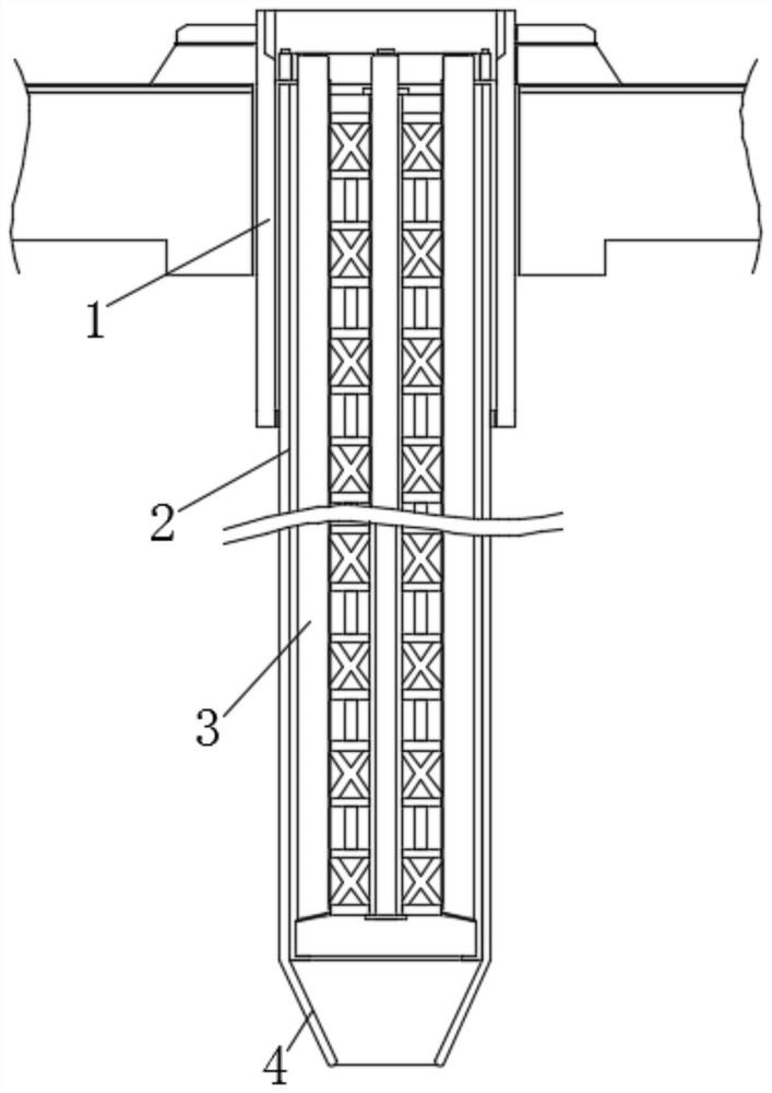
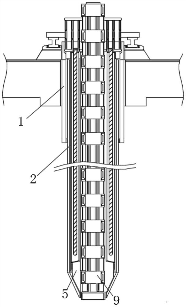
[0045] Example 1, as Figure 1-3 As shown, after the casing 1 is assembled, the outer reinforcement frame 2 is then inserted into the inner layer of the casing 1 in turn, and then the inner reinforcement cage 5 is inserted into the inner layer of the outer reinforcement frame 2, and the axial center of the bottom surface of the inner reinforcement cage 5 Prefabricated hollow tube 6 and concrete channel 7, the lattice column 9 can be inserted into the inner layer of the inner steel cage 5 at this time, and wrapped on the outer wall of the hollow tube 6, so that the internal structure of the formed uplift pile is interconnected and strengthened The anti-offset and bearing capacity of the pile body make the installation work distinct, and enhance the work efficiency of the on-site loading and installation of the uplift pile.

Embodiment 2

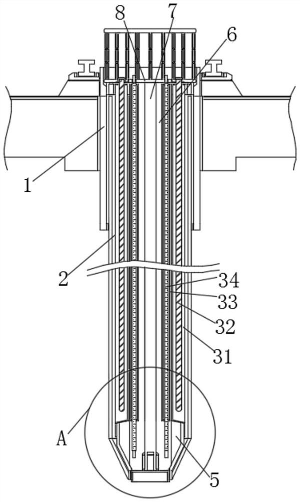
[0046] Example 2, as Figure 4-7 As shown, the reinforcement fence 8 can be prefabricated above the inner reinforcement cage 5, so that the reinforcement fence 8 is higher than the ground at a certain height, and after the protective tube 1, the outer reinforcement frame 2, the inner reinforcement cage 5 and the lattice column 9 are loaded and installed , four groups of prestressed steel strands 32 embedded in the inner cavity of the hollow limit post 31 and the planting bars 34 in the inner cavity of the square tube 33 can be driven above the reinforced fence 8, and finally the filled concrete can be extended to the hollow limit. The inner cavity of the position column 31 and the square tube 33 makes the inner layer filling of the outer reinforcement frame 2 and the inner reinforcement cage 5 more compact, and increases the prestress and the pullout resistance of the pullout pile anchoring structure.

[0047] Example 2, as Figure 8-10 As shown, when the crawler crane 12 is ...


PUM


Abstract

The prestressed post-inserted composite anchor cable uplift pile comprises a pile casing, an outer steel bar frame is inserted into the inner side of the pile casing, a cone-shaped body with a guide device is arranged at the bottom of the outer steel bar frame, an inner steel bar cage is inserted into the inner side of the outer steel bar frame, and the inner steel bar cage is arranged in the outer steel bar frame. A hollow pipe is fixedly connected to the axis of the bottom of the interior of the inner reinforcement cage, a concrete pouring channel is formed in the center of the interior of the hollow pipe, and through openings are evenly formed in the bottom of the outer side of the concrete pouring channel. Through the structural cooperation of the pile casing, the outer steel bar frame, the inner steel bar cage and the latticed column, the structural system of the uplift pile is made to be well arranged during installation work, a positioning guide structure between the structures can be formed through structural traction of the guide mechanism, it is guaranteed that vertical installation of the uplift pile body is more accurate and centered, and the construction efficiency is improved. The phenomena of inclination and position deviation of the post-inserted uplift pile are reduced, and meanwhile the tensile stress of the uplift pile body in the working state is eliminated.

Description

technical field [0001] The invention relates to the technical field of underground construction, in particular to a prestressed post-insertion composite anchor cable uplift pile and its on-site loading equipment. Background technique [0002] Anti-uplift piles are widely used in large-scale basement anti-floating, high-rise building anti-uplift, offshore dock platform uplift, suspension bridge and cable-stayed bridge anchor pile foundation, large dock floor pile foundation and static load test pile anchor pile foundation, etc. , refers to the piles that are driven in order to offset the buoyancy of the structure produced by the water in the soil when the underground structure of the construction project is lower than the surrounding soil water level. [0003] Authorized Announcement No. CN113152535B Patent discloses the construction method of back-inserted unbonded steel strand pressure-bearing anti-uplift pile and the combination used. The composite body formed by the stee...

Claims


Application Information

Patent Timeline
Patent Type & Authority Applications(China)
IPC IPC(8): E02D5/34E02D5/58E02D31/06E02D31/12E02D33/00
CPCE02D5/34E02D5/58E02D31/06E02D31/12E02D33/00
Inventor 毛宗原张强郭豪张吉柱
Owner CHINA ACAD OF BUILDING RES
Why Eureka
Try Eureka