
Polarization resolution fluorescence testing system based on three-dimensional movable light path

A polarization resolution and testing system technology, which is applied in the field of fluorescence spectrum detection, can solve the problems that the fluorescence spectrum test system cannot meet the measurement requirements and huge research needs, and achieve the effect of eliminating polarization detection errors and reducing polarization detection errors

Pending Publication Date: 2022-06-28
NAT UNIV OF DEFENSE TECH
View PDF0 Cites 0 Cited by
  • Summary
  • Abstract
  • Description
  • Claims
  • Application Information

AI Technical Summary

Problems solved by technology

[0005] In addition, in terms of polarization detection, there are also two major problems to be solved. One is that the excitation light and fluorescence will experience a large number of reflections from optical lenses in the system. How to ensure that the excitation light incident on the sample and reflected to the entrance of the spectral detector The polarization degree of the fluorescence at the place; the second is that the general spectrometer uses a wire grid grating for wavelength resolution, which itself has different polarization response characteristics to the fluorescence of different wavelengths. How to reduce the systematic polarization detection error caused by the spectral detection device
[0006] There is a huge demand for research on low-temperature polarization fluorescence spectroscopy detection of current low-dimensional semiconductor materials, and traditional fluorescence spectroscopy testing systems cannot meet the measurement requirements

Method used


Image

  • Polarization resolution fluorescence testing system based on three-dimensional movable light path
  • Polarization resolution fluorescence testing system based on three-dimensional movable light path

Examples


Embodiment Construction

[0035] The preferred embodiments of the present invention will be described in detail below with reference to the accompanying drawings, so that the advantages and features of the present invention can be more easily understood by those skilled in the art, and the protection scope of the present invention can be more clearly defined.

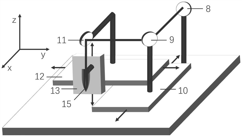
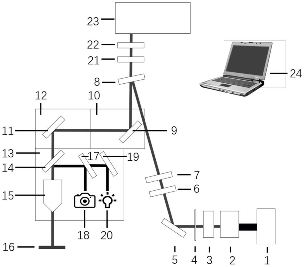
[0036] see figure 1 and figure 2As shown, this embodiment discloses a polarization-resolved fluorescence test system based on a three-dimensional movable optical path, including: a laser generating component for generating excitation light; a laser polarization adjusting component for adjusting the polarization state of the excitation light; The filter 8 is used to reflect the excitation light and transmit the fluorescence emitted by the sample; the three-dimensional independent optical path displacement component is used to three-dimensionally adjust the optical path to focus the light spot on the sample surface to perform independent movement...


PUM

PropertyMeasurementUnit
Angle of incidenceaaaaaaaaaa

Abstract

The invention discloses a polarization resolution fluorescence test system based on a three-dimensional movable light path, which comprises a laser generation assembly used for generating exciting light; the laser polarization adjusting assembly is used for adjusting the polarization state of the exciting light; the optical filter is used for reflecting the exciting light and transmitting fluorescent light emitted by a sample; the three-dimensional independent light path displacement assembly is used for adjusting a light path in a three-dimensional manner so as to focus a light spot to independently move on the surface of the sample on the x axis, the y axis and the z axis; the microscope system is used for carrying out illumination and microscopic imaging on the surface appearance, the exciting light and the fluorescent light of the sample; the fluorescence polarization adjusting assembly is used for adjusting the polarization state of fluorescence; and the spectrum detection module is used for detecting the spectrum and the service life of the fluorescence. The device has the characteristics that a sample does not move and a light path moves, can be compatible with most non-displaceable cryostats on the market, and realizes any circular polarization or linear polarization fluorescence detection by adopting polarization adjustable components and a small-angle incidence mode.

Description

technical field [0001] The invention relates to the technical field of fluorescence spectrum detection, more particularly, to a polarization-resolved fluorescence testing system based on a three-dimensional movable optical path. Background technique [0002] As a type of fermions, electrons naturally have two intrinsic properties: charge and spin. The development of charge-type devices and spin-type devices by carrying information with the charge and spin of electrons is the cornerstone of the current information technology industry. With the advent of the information age, many practical demands such as larger capacity, faster transmission, and lower power consumption not only promote the progress of the industrial technology chain, but also stimulate people's enthusiasm for exploring new electronic degrees of freedom in the field of basic research. In recent years, with the emergence of two-dimensional materials such as graphene and transition metal chalcogenides, new elec...

Claims


Application Information

Patent Timeline
IPC IPC(8): G01N21/64
CPCG01N21/6445G01N21/6458G01N2021/6417
Inventor 韦可隋沂臻江天唐宇翔刘祺瑞李思维程湘爱
Owner NAT UNIV OF DEFENSE TECH
Learn More