
Optical module

An optical module and laser technology, applied in the field of optical modules, can solve problems such as changes in optical mechanisms, affecting the normal operation of optical modules, and optical surface pollution.

Pending Publication Date: 2022-06-28
HISENSE BROADBAND MULTIMEDIA TECH
View PDF0 Cites 1 Cited by
  • Summary
  • Abstract
  • Description
  • Claims
  • Application Information

AI Technical Summary

Problems solved by technology

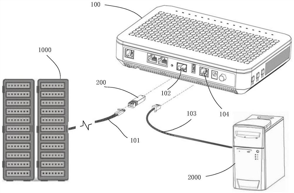
[0004] However, due to the low-cost requirements of the optical modules deployed in the data center, the light emitting and receiving components mostly use non-sealed design structures, and their key optical paths are all open. When the optical modules enter the cooling liquid with the switch, these key optical paths And components will also enter the cooling liquid, resulting in changes in the optical mechanism and pollution of the optical surface, seriously affecting the normal operation of the optical module

Method used


Image

  • Optical module
  • Optical module
  • Optical module

Examples


Embodiment Construction

[0048]The technical solutions in some embodiments of the present disclosure will be clearly and completely described below with reference to the accompanying drawings. Obviously, the described embodiments are only a part of the embodiments of the present disclosure, but not all of the embodiments. All other embodiments obtained by those of ordinary skill in the art based on the embodiments provided by the present disclosure fall within the protection scope of the present disclosure.

[0049] Unless the context otherwise requires, throughout the specification and claims, the term "comprise" and its other forms such as the third person singular "comprises" and the present participle "comprising" are used It is interpreted as the meaning of openness and inclusion, that is, "including, but not limited to". In the description of the specification, the terms "one embodiment", "some embodiments", "exemplary embodiments", "example", "specific example" example)" or "some examples" and...


PUM


Abstract

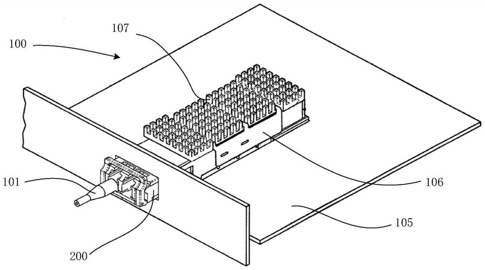
The optical module provided by the invention comprises a circuit board and a light emitting assembly, wherein the circuit board is provided with a jack with an opening in one side; the light emitting assembly comprises a second emitting shell, an upper cover plate, a laser, a second light path translation prism and a light collimator, a clamping groove is formed in the outer side wall of the second emitting shell, the clamping groove is inserted into the insertion hole through the opening, the upper side of the clamping groove is located on the front side of the circuit board, and the lower side of the clamping groove is located on the back side of the circuit board; the second emission shell comprises a mounting groove, and the upper cover plate covers the opening side of the top surface of the mounting groove; one end of the mounting groove is provided with a notch, and the circuit board on one side of the jack extends into the notch for sealing connection; the laser is arranged in the mounting groove and is electrically connected with the circuit board extending into the notch; the second light path translation prism is arranged in the mounting groove and is used for upwards moving the laser beam on the front surface of the circuit board; one end of the optical collimator is inserted into the mounting groove, and the other end is hermetically connected with the optical fiber. According to the invention, through the unique structural design of the light emitting assembly, the light path is completely sealed and packaged.

Description

technical field [0001] The present application relates to the technical field of optical fiber communication, and in particular, to an optical module. Background technique [0002] With the development of new business and application models such as cloud computing, mobile Internet, and video, the development and progress of optical communication technology has become more and more important. In the optical communication technology, the optical module is a tool for realizing the mutual conversion of photoelectric signals, and it is one of the key components in the optical communication equipment. With the development of the optical communication technology, the transmission rate of the optical module continues to increase. [0003] With the increase of the communication rate, although the power consumption per unit bandwidth is decreasing, the overall power consumption of the optical module is still further increasing. Most of the heat dissipation methods used in the client e...

Claims


Application Information

Patent Timeline
Patent Type & Authority Applications(China)
IPC IPC(8): G02B6/42
CPCG02B6/4245G02B6/4268G02B6/428
Inventor 吴涛邵乾慕建伟
Owner HISENSE BROADBAND MULTIMEDIA TECH
Learn More