Sliding mode current compensation control system and method for switched reluctance motor

A switched reluctance motor and current compensation technology, which is applied in control systems, motor control, AC motor control, etc., can solve problems such as torque ripple, nonlinear characteristics of phase inductance, and limited control performance, and achieve torque ripple suppression, Effect of Suppressing Commutation Torque Ripple

Active Publication Date: 2022-06-28
GUANGDONG UNIV OF TECH
View PDF8 Cites 1 Cited by
  • Summary
  • Abstract
  • Description
  • Claims
  • Application Information

AI Technical Summary

Problems solved by technology

[0002] The structural feature of the switched reluctance motor (SRM) is that the rotor has neither windings nor permanent magnets, the stator poles are wound with concentrated windings, and the two radially opposite windings are connected to form a phase, which has the advantages of simple structure and reliable driving circuit. High, large starting torque, especially suitable for frequent start-stop applications, and is expected to become the first choice for the power source of the next generation of new energy vehicles, but the double salient pole structure of the switched reluctance motor causes serious nonlinear characteristics of its phase inductance, It makes the torque ripple more serious when it is work

Method used


Image

  • Sliding mode current compensation control system and method for switched reluctance motor
  • Sliding mode current compensation control system and method for switched reluctance motor
  • Sliding mode current compensation control system and method for switched reluctance motor

Examples


Embodiment Construction

[0053] The present invention will be further described in detail below with reference to the accompanying drawings and specific embodiments. The numbers of the steps in the following embodiments are set only for the convenience of description, and the sequence between the steps is not limited in any way, and the execution sequence of each step in the embodiments can be adapted according to the understanding of those skilled in the art Sexual adjustment.

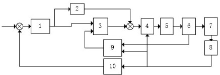
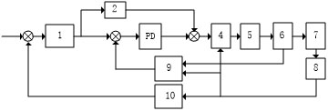
[0054] refer to figure 1 The present invention provides a sliding mode current compensation control system for a switched reluctance motor, including a PID speed controller 1, a feedforward calculation module 2, a sliding mode current compensation module 3, a current distribution module 4, a current hysteresis module 5, a Symmetrical half-bridge drive circuit 6, switched reluctance motor 7, encoder 8, torque calculation module 9 and rotational speed calculation module 10, the input end of the PID speed controller 1 is connec...


PUM


Abstract

The invention discloses a switched reluctance motor sliding mode current compensation control system and method. The system comprises a PID speed controller, a feedforward calculation module, a sliding mode current compensation module, a current distribution module, a current hysteresis module, an asymmetric half-bridge drive circuit, a switched reluctance motor, an encoder, a torque calculation module and a rotating speed calculation module. According to the invention, differential calculation processing is carried out on the rotating speed error signal through the PID speed controller and compensation is carried out on the input current of the switched reluctance motor through the sliding mode current compensation module, so that the commutation torque ripple of the switched reluctance motor can be effectively suppressed in the process of improving the load of the switched reluctance motor. The switched reluctance motor sliding mode current compensation control system and method can be widely applied to the technical field of switched reluctance motor speed regulation control.

Description

technical field [0001] The invention relates to the technical field of speed regulation control of switched reluctance motors, in particular to a sliding mode current compensation control system and method for switched reluctance motors. Background technique [0002] The structural feature of the switched reluctance motor (SRM) is that the rotor has neither windings nor permanent magnets, the stator poles are wound with concentrated windings, and the two radially opposite windings are connected to form one phase, with simple structure and reliable driving circuit. high starting torque, especially suitable for applications with frequent start and stop, and is expected to become the first choice for the power source of the next-generation new energy vehicles, but the double salient structure of the switched reluctance motor causes serious nonlinear characteristics of its phase inductance. This makes the torque ripple more serious during operation, which limits its application ...

Claims


Application Information

Patent Timeline
IPC IPC(8): H02P23/00H02P23/14H02P25/098
CPCH02P23/0009H02P23/14H02P25/098H02P2203/03
Inventor 李琴罗配明张学习彭祖群
Owner GUANGDONG UNIV OF TECH
Why Eureka
Try Eureka