Supercharge Your Innovation With Domain-Expert AI Agents!

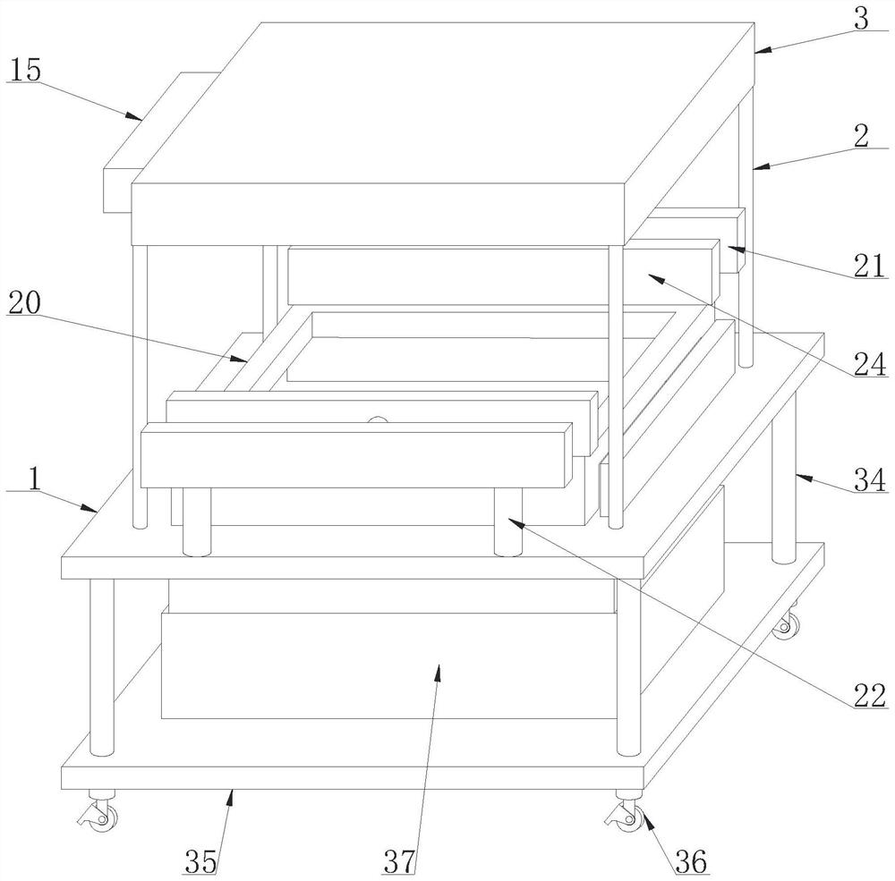
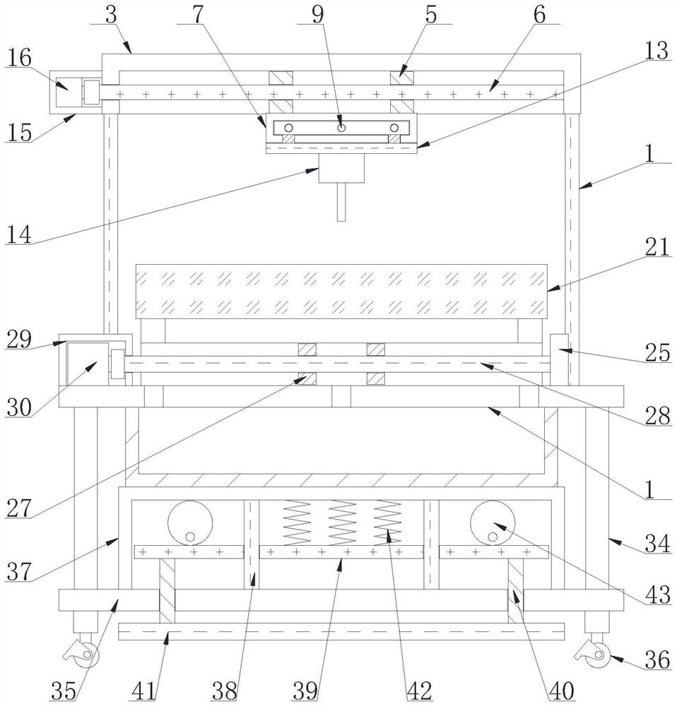
Positioning drilling machine for computer machining

A drilling machine and computer technology, applied in the field of positioning drilling machinery, can solve the problems of positioning drilling, difficult cleaning of debris during drilling, and affecting drilling accuracy.

Pending Publication Date: 2022-07-01
淮安生物工程高等职业学校
View PDF10 Cites 0 Cited by
  • Summary
  • Abstract
  • Description
  • Claims
  • Application Information

AI Technical Summary

Problems solved by technology

[0004] In order to solve the shortcomings of the existing technology, the position of the drill can be adjusted by using the positioning structure, which is convenient for positioning and drilling at different positions of the computer board, and solves the problem that the existing drilling machinery is difficult to position and drill at different positions of the computer board , to avoid dismantling the computer plate for drilling processing many times, improve the efficiency of computer plate drilling and processing, and facilitate computer processing
[0005] In order to solve the problems in the prior art, the auxiliary structure can be used to clamp the computer board to prevent the position of the computer board from moving during drilling and affect the drilling effect. At the same time, the debris generated during drilling can be cleaned. It solves the problem that the debris is difficult to clean when the existing drilling machine is drilling, and it is convenient to keep the table top of the drilling machine clean
[0006] Further, in order to solve the problems in the prior art, the use of the support structure can make the drilling machine more stable when in use, and solve the problem that the existing drilling machine is prone to move during use and affect the drilling accuracy, which is convenient for computer drilling. hole processing

Method used


Image

  • Positioning drilling machine for computer machining
  • Positioning drilling machine for computer machining
  • Positioning drilling machine for computer machining

Examples


Embodiment Construction

[0030] In order to make the application purpose, features and advantages of the present application more obvious and understandable, the technical solutions in the embodiments of the present application will be described clearly and completely below with reference to the accompanying drawings in the embodiments of the present application. Obviously, the following The described embodiments are only some, but not all, embodiments of the present application. Based on the embodiments in this application, all other embodiments obtained by those of ordinary skill in the art without creative efforts shall fall within the protection scope of this application.

[0031] The technical solutions of the present application will be further described below with reference to the accompanying drawings and through specific embodiments.

[0032] In the description of the present application, it should be understood that the orientations or positional relationships indicated by the terms "upper",...


PUM


Abstract

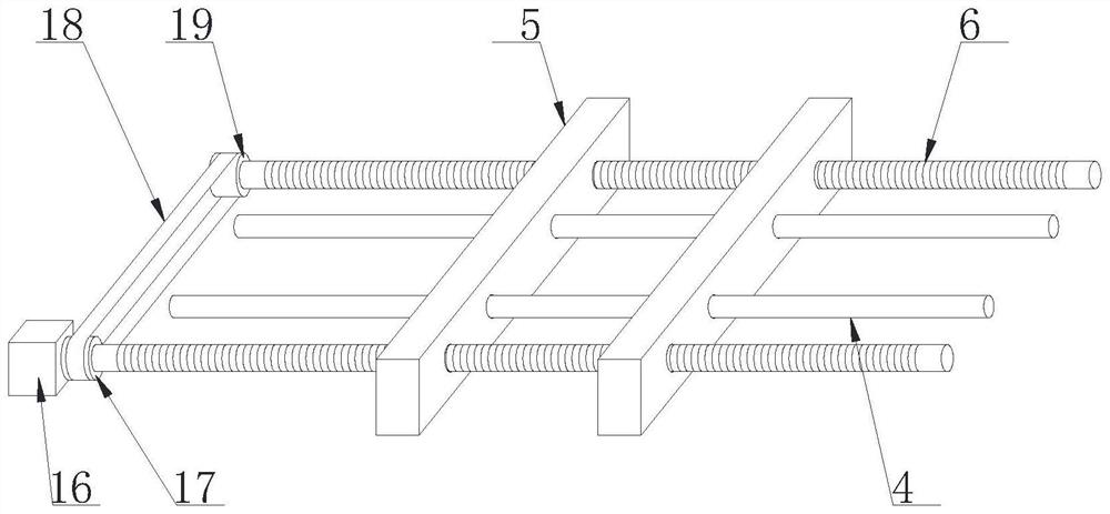
The positioning drilling machine for computer machining comprises a positioning structure, the positioning structure comprises a supporting plate, a fixing column is fixedly connected to the top of the supporting plate, a fixing shell is fixedly connected to the top end of the fixing column, a first limiting column is fixedly connected to the side wall of an inner cavity of the fixing shell, and an adjusting plate is slidably connected to the surface of the first limiting column; the adjusting plate is in threaded connection with the surface of the first one-way threaded column, one end of the first one-way threaded column is connected with the driving assembly, the driving assembly is fixedly connected to one side of the fixed shell, the bottom of the adjusting plate is fixedly connected with the adjusting shell, one side of the adjusting shell is fixedly connected with the adjusting motor, and the output end of the adjusting motor is fixedly connected with the second one-way threaded column. The surface of the second one-way threaded column is in threaded connection with a first moving plate, and the first moving plate is slidably connected to the surface of the second limiting column. The positioning drilling machine for computer machining has the beneficial effect that the positioning drilling machine for computer machining is convenient to adjust and clean.

Description

technical field [0001] The present application relates to a drilling machine, in particular to a positioning drilling machine for computer processing. Background technique [0002] Computer, commonly known as computer, is a modern electronic computing machine used for high-speed computing. It can perform numerical calculations and logical calculations. It also has storage and memory functions. Equipment, a computer consists of a hardware system and a software system. A computer without any software is called a bare metal. It can be divided into five categories: supercomputer, industrial control computer, network computer, personal computer, and embedded computer. The more advanced computers have biological Computers, photonic computers, quantum computers, etc., the evolution of computing tools has gone through different stages from simple to complex, from low-level to high-level, such as from the rope knot in "Notes on Knotting the Rope" to calculating chips, abacus slide ru...

Claims


Application Information

Patent Timeline
IPC IPC(8): B23B41/00B23B47/20B23Q3/06
CPCB23B41/00B23Q5/28B23Q3/06
Inventor 仲春雷
Owner 淮安生物工程高等职业学校
Features
  • R&D
  • Intellectual Property
  • Life Sciences
  • Materials
  • Tech Scout
  • Unparalleled Data Quality
  • Higher Quality Content
  • 60% Fewer Hallucinations
Learn More