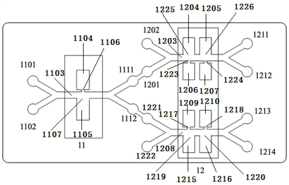
[0038] It should be noted that the embodiments of the present invention and the features of the embodiments may be combined with each other under the condition of no conflict. The present invention will be described in detail below with reference to the accompanying drawings and in conjunction with the embodiments.
[0039] In order to make the purposes, technical solutions and advantages of the embodiments of the present invention clearer, the technical solutions in the embodiments of the present invention will be clearly and completely described below with reference to the accompanying drawings in the embodiments of the present invention. Obviously, the described embodiments It is only a part of the embodiments of the present invention, but not all of the embodiments. The following description of at least one exemplary embodiment is merely illustrative in nature and is in no way intended to limit the invention, its application, or uses. Based on the embodiments of the present invention, all other embodiments obtained by those of ordinary skill in the art without creative efforts shall fall within the protection scope of the present invention.
[0040] It should be noted that the terminology used herein is for the purpose of describing specific embodiments only, and is not intended to limit the exemplary embodiments according to the present invention. As used herein, unless the context clearly dictates otherwise, the singular is intended to include the plural as well, furthermore, it is to be understood that when the terms "comprising" and/or "including" are used in this specification, it indicates that There are features, steps, operations, devices, components and/or combinations thereof.
[0041] The relative arrangement of the components and steps, the numerical expressions and numerical values set forth in these embodiments do not limit the scope of the invention unless specifically stated otherwise. Meanwhile, it should be understood that, for convenience of description, the dimensions of various parts shown in the accompanying drawings are not drawn in an actual proportional relationship. Techniques, methods, and devices known to those of ordinary skill in the relevant art may not be discussed in detail, but where appropriate, such techniques, methods, and devices should be considered part of the authorized specification. In all examples shown and discussed herein, any specific values should be construed as illustrative only and not limiting. Accordingly, other examples of exemplary embodiments may have different values. It should be noted that like numerals and letters refer to like items in the following figures, so once an item is defined in one figure, it does not require further discussion in subsequent figures.
[0042] In the description of the present invention, it should be understood that the orientations indicated by orientation words such as "front, rear, top, bottom, left, right", "horizontal, vertical, vertical, horizontal" and "top, bottom" etc. Or the positional relationship is usually based on the orientation or positional relationship shown in the drawings, which is only for the convenience of describing the present invention and simplifying the description, and these orientations do not indicate or imply the indicated device or element unless otherwise stated. It must have a specific orientation or be constructed and operated in a specific orientation, so it should not be construed as a limitation on the scope of protection of the present invention: the orientation words "inside and outside" refer to the inside and outside relative to the contour of each component itself.
[0043] For ease of description, spatially relative terms such as "on", "over", "on the surface", "above", etc., may be used herein to describe what is shown in the figures. The spatial positional relationship of one device or feature shown to other devices or features. It should be understood that spatially relative terms are intended to encompass different orientations of the device in use or operation in addition to the orientation depicted in the figures. For example, if the device in the figures is turned over, elements described as "above" or "over" other devices or features would then be oriented "below" or "over" the other devices or features under its device or structure". Thus, the exemplary term "above" can encompass both an orientation of "above" and "below." The device may also be otherwise oriented (rotated 90 degrees or at other orientations) and the spatially relative descriptions used herein interpreted accordingly.
[0044] In addition, it should be noted that the use of words such as "first" and "second" to define components is only for the convenience of distinguishing corresponding components. Unless otherwise stated, the above words have no special meaning and therefore cannot be understood to limit the scope of protection of the present invention.
[0045] like figure 1 As shown, the present invention provides a marine microplastic particle identification and detection device combined with dielectrophoresis and laser-induced breakdown spectroscopy, including: a marine microplastic particle sorting device, a marine microplastic particle identification and detection device, and a display; wherein:
[0046] The marine microplastic particle sorting device uses a microfluidic chip as a sorting platform, and generates an uneven electric field with the help of asymmetric through holes, and the marine microplastic particles in the area of the uneven electric field are polarized and subjected to dielectrophoresis force (Dielectrophoresis). , DEP), using the difference of dielectrophoresis force to realize the multi-stage sorting of marine microplastic particles; in this embodiment, the marine microplastic particle sorting device uses a microfluidic chip as the sorting platform Different marine microplastic particles are sorted to different outlets. Dielectrophoresis refers to the phenomenon that particles are polarized in a non-uniform electric field to produce motion, which is related to the size and dielectric properties of microparticles. It has the advantages of label-free operation and the ability to induce contact-free positive or negative forces. In a non-uniform electric field, a particle of radius r is subjected to the dielectrophoretic force as follows:
[0047]
[0048] The marine microplastic particle identification and detection device adopts a laser-induced breakdown spectrometer (Laser-InducedBreakdown Spectroscopy, LIBS). Substances, and the spectrum emitted by the atoms excited by the plasma is obtained by the spectrometer, so as to identify the elemental composition in the sample, and then the identification, classification, qualitative and quantitative analysis of materials can be carried out. It requires almost no sample preparation, can be analyzed directly and quickly, and can detect almost all solid samples, enabling the qualitative analysis of marine microplastic particles.
[0049] The display, assisting the laser-induced breakdown spectrometer, displays the spectrum of the identified sample, and uses the supporting software to realize the identification and detection of marine microplastic particles.
[0050] The microfluidic chip in the present invention generates an uneven electric field by means of asymmetric through holes, and the marine microplastic particles are polarized when they are in the uneven electric field area, and are subjected to a dielectrophoretic force. The multi-stage sorting of marine microplastic particles with different sizes can be realized by using the difference of dielectrophoretic force.
[0051] In specific implementation, as a preferred embodiment of the present invention, the marine microplastic particle sorting device adopts a two-stage sorting microfluidic chip, and a primary sorting area and a secondary sorting area are arranged in the chip; The ITO electrode of the wire between the wire and the 3D microelectrode layer; the non-uniform electric field is generated by asymmetric through holes in the primary sorting area and the secondary sorting area.
[0052] During specific implementation, as a preferred embodiment of the present invention, the first-level sorting area is provided with a first-level microfluidic channel, a group of asymmetric through holes, and a first-level 3D microelectrode layer; wherein:
[0053] One side of the first-level microfluidic channel is respectively connected with the first-level sorting sample inlet and the first-level sheath fluid inlet, and the other side of the first-level microfluidic channel is respectively connected with the first-level outlet I and the first-level outlet II; One side wall of the channel is respectively provided with a first through hole, and the other side wall corresponding to the first through hole is provided with a second through hole, and the first through hole and the second through hole constitute a group of asymmetric through holes;
[0054] The first-level 3D microelectrode layer includes a first-level 3D microelectrode I and a first-level 3D microelectrode II respectively arranged on both sides of the first-level microfluidic channel.
[0055] A set of asymmetric through-holes are set in the primary sorting to complete the sorting of marine microplastic particles with large differences in size, such as the sorting of micron-scale marine microplastic particles and nano-scale marine microplastic particles. Marine microplastic particles flow into different outlets and continue to complete secondary sorting.
[0056] In specific implementation, as a preferred embodiment of the present invention, the secondary sorting area is provided with a secondary microfluidic channel I, a secondary microfluidic channel II, two groups of asymmetric through holes, a secondary 3D microelectrode layer I and two grade 3D microelectrode layer II; where:
[0057] One side of the secondary microfluidic channel I is respectively connected with the secondary sample inlet I and the secondary sheath liquid inlet I, and the secondary sample inlet I is connected with the primary outlet I; the other side of the secondary microfluidic channel I is connected with two A third through hole and a fourth through hole are respectively provided on one side wall of the secondary microfluidic channel I, and the other side wall corresponding to the third through hole is provided with a fifth through hole, corresponding to The other side wall of the fourth through hole is provided with a sixth through hole; the third through hole and the fifth through hole constitute a group of asymmetric through holes; the fourth through hole and the sixth through hole constitute another group of asymmetric through holes ;
[0058] One side of the secondary microfluidic channel II is connected with the secondary sample inlet II and the secondary sheath fluid inlet II, respectively, and the secondary sample inlet II is connected with the primary outlet II; the other side of the secondary microfluidic channel I is connected with two A seventh through hole and an eighth through hole are respectively set on one side wall of the second stage microfluidic channel I, and the other side wall corresponding to the seventh through hole is provided with a ninth through hole, corresponding to The other side wall of the eighth through hole is provided with a tenth through hole; the seventh through hole and the ninth through hole constitute a group of asymmetric through holes; the eighth through hole and the tenth through hole constitute another group of asymmetric through holes ;
[0059] The secondary 3D microelectrode layer I includes two pairs of secondary 3D microelectrodes arranged on both sides of the secondary microfluidic channel I, namely, the secondary 3D microelectrode I, the secondary 3D microelectrode II, the secondary 3D microelectrode III and the secondary 3D microelectrode. Secondary 3D Microelectrode IV;
[0060] The secondary 3D microelectrode layer II includes two pairs of secondary 3D microelectrodes arranged on both sides of the secondary microfluidic channel II, namely the secondary 3D microelectrode V, the secondary 3D microelectrode VI, the secondary 3D microelectrode VII and the secondary 3D microelectrode. Secondary 3D Microelectrode VII.
[0061] In the secondary sorting, two sets of asymmetric through-holes are set, which expands the area of uneven electric field, prolongs the stress time, and completes the sorting of marine microplastic particles with small size differences, such as micron-scale marine microplastic particles. Sorting or sorting of nano-scale marine microplastic particles.
[0062] In specific implementation, as a preferred embodiment of the present invention, the first-level 3D microelectrode I, the first-level 3D microelectrode II, the second-level 3D microelectrode I, the second-level 3D microelectrode II, the second-level 3D microelectrode III, and the second-level 3D microelectrode II Grade 3D microelectrode Ⅳ, secondary 3D microelectrode Ⅴ, secondary 3D microelectrode Ⅵ, secondary 3D microelectrode Ⅶ and secondary 3D microelectrode Ⅶ all use copper electrodes.
[0063] During specific implementation, as a preferred embodiment of the present invention, in the asymmetric through hole, the diameter of the large hole is 520 um, and the diameter of the small hole is 10 um.
[0064] The present invention also provides a method for identifying and detecting marine microplastic particles based on the above-mentioned combination of dielectrophoresis and laser-induced breakdown spectroscopy for identifying and detecting marine microplastic particles. work, including the following steps:
[0065] S1. Put the marine microplastic particle sorting device into the plasma cleaning machine for cleaning, connect the voltage source to energize after cleaning, add marine microplastic particles of different types and sizes, and observe the experimental phenomenon and experimental results under a microscope;
[0066] S2. Take out the sorted marine microplastic particles for drying;
[0067] S3. Put the dried marine microplastic particles into the laser-induced breakdown spectrometer, turn on the display at the same time, and complete the identification and detection of the marine microplastic particles with the aid of the software of the laser-induced breakdown spectrometer.
[0068] In this embodiment, the sorting samples do not need too much pretreatment, and the identification and detection samples only need to be dried. The sorting, identification and detection process of marine microplastic particles is simple and rapid, and there are no excessive requirements for the experimenter, just master the correct method, and the test results are accurate and repeatable.
[0069] Finally, it should be noted that the above embodiments are only used to illustrate the technical solutions of the present invention, but not to limit them; although the present invention has been described in detail with reference to the foregoing embodiments, those of ordinary skill in the art should understand that: The technical solutions described in the foregoing embodiments can still be modified, or some or all of the technical features thereof can be equivalently replaced; and these modifications or replacements do not make the essence of the corresponding technical solutions deviate from the technical solutions of the embodiments of the present invention. scope.