Supercharge Your Innovation With Domain-Expert AI Agents!

Control method of multi-phase interleaving inverter circuit, power conversion device and energy storage equipment

An inverter circuit, multi-phase interleaving technology, applied in the output power conversion device, the conversion of AC power input to DC power output, electrical components and other directions, can solve the problems of increased loss, low conversion efficiency, etc., to reduce loss, Improve the effect of switch control logic

Pending Publication Date: 2022-07-01
ECOFLOW TECH LTD
View PDF0 Cites 2 Cited by
  • Summary
  • Abstract
  • Description
  • Claims
  • Application Information

AI Technical Summary

Problems solved by technology

[0004] The purpose of this application is to provide a control method for a multi-phase interleaved inverter circuit, a power conversion device, and an energy storage device, aiming at solving the problem of increased loss caused by maintaining multi-tube operation when the inverter is light-loaded or no-loaded , there is a problem of low conversion efficiency

Method used

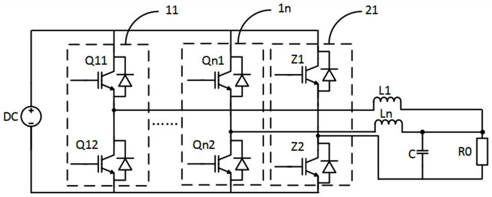
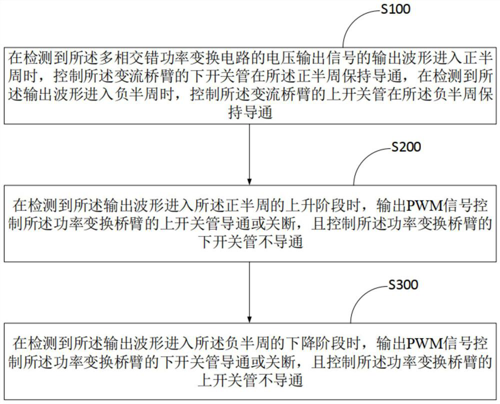
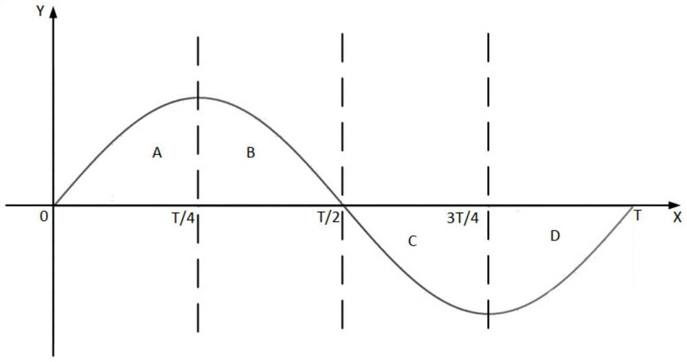

Image

  • Control method of multi-phase interleaving inverter circuit, power conversion device and energy storage equipment
  • Control method of multi-phase interleaving inverter circuit, power conversion device and energy storage equipment
  • Control method of multi-phase interleaving inverter circuit, power conversion device and energy storage equipment

Examples


Embodiment Construction

[0041] In order to make those skilled in the art better understand the solutions of the present application, the technical solutions in the embodiments of the present application will be clearly described below with reference to the accompanying drawings in the embodiments of the present application. Obviously, the described embodiments are of the present application. Some examples, but not all examples. Based on the embodiments in the present application, all other embodiments obtained by those of ordinary skill in the art without creative work shall fall within the protection scope of the present application.

[0042] The term "comprising" and any variations thereof in the description and claims of this application and the above-mentioned drawings are intended to cover non-exclusive inclusion. For example, a process, method or system, product or device comprising a series of steps or units is not limited to the listed steps or units, but optionally also includes unlisted ste...


PUM


Abstract

The invention belongs to the technical field of converter control, and provides a control method of a multi-phase interleaving inverter circuit, a power conversion device and energy storage equipment, when it is detected that an output waveform of a voltage output signal of the multi-phase interleaving inverter circuit enters a positive half cycle, a lower switch tube of a converter bridge arm is controlled to be kept on in the positive half cycle, and the output waveform of the voltage output signal enters the negative half cycle. When it is detected that the output waveform enters the negative half cycle, an upper switch tube of the converter bridge arm is controlled to be kept on in the negative half cycle, and when it is detected that the output waveform enters the rising stage of the positive half cycle, an upper switch tube of the power conversion bridge arm is controlled to be on or off, and a lower switch tube of the power conversion bridge arm is controlled not to be on; when it is detected that the output waveform enters the descending stage of the negative half cycle, a lower switching tube of the power conversion bridge arm is controlled to be switched on or switched off, and an upper switching tube of the power conversion bridge arm is controlled not to be switched on. By improving the switching control logic of the alternating current bridge arm and the power conversion bridge arm, the loss of the multi-phase interlaced inverter circuit under the no-load condition is reduced.

Description

technical field [0001] The present application belongs to the technical field of converter control, and in particular relates to a control method of a multi-phase staggered inverter circuit, a power conversion device, and an energy storage device. Background technique [0002] A bidirectional inverter is a converter that converts DC power into AC power. In the working process of the traditional multi-phase interleaved inverter, in order to improve the efficiency, there are usually two switching tubes (ie, power frequency switching tubes) working at the fundamental frequency, and four switching tubes at the high frequency ( switching frequency) work switch tube (ie high frequency switch tube). In a power frequency cycle, it is necessary to maintain a power frequency switch tube and a corresponding high frequency switch tube to work at the same time. [0003] However, when the converter is light-loaded or no-loaded, maintaining multiple switches to work simultaneously in one...

Claims


Application Information

Patent Timeline
IPC IPC(8): H02M7/5387H02M1/088
CPCH02M7/5387H02M1/088
Inventor 张宏韬陈熙
Owner ECOFLOW TECH LTD
Features
  • R&D
  • Intellectual Property
  • Life Sciences
  • Materials
  • Tech Scout
  • Unparalleled Data Quality
  • Higher Quality Content
  • 60% Fewer Hallucinations
Learn More