Circularly polarized microstrip antenna with low profile, high gain and wide axial ratio beam

A microstrip antenna, high gain technology, applied in slot antenna, antenna grounding device, antenna grounding switch structure connection, etc., can solve the problem of reducing impedance bandwidth and antenna gain, large antenna structure, narrow 3-dB half-power beam width, etc. problem, to achieve the effect of wide-axis ratio beam width and increasing physical size

Pending Publication Date: 2022-07-05
HANGZHOU DIANZI UNIV
View PDF4 Cites 0 Cited by
  • Summary
  • Abstract
  • Description
  • Claims
  • Application Information

AI Technical Summary

Problems solved by technology

Although this method can relatively increase the axial ratio beamwidth, it will reduce the impedance bandwidth and antenna gain
Also, some take the form of folded dipoles, however, this approach results in a narrow 3-dB half-power beamwidth and a relatively large antenna structure

Method used


Image

  • Circularly polarized microstrip antenna with low profile, high gain and wide axial ratio beam
  • Circularly polarized microstrip antenna with low profile, high gain and wide axial ratio beam
  • Circularly polarized microstrip antenna with low profile, high gain and wide axial ratio beam

Examples


Embodiment Construction

[0036] The following is to explain the technical solutions, design purposes and advantages of the present invention more clearly. The present invention will be described in more detail with reference to the embodiments and the accompanying drawings. The specific embodiments used here are only for illustration and are not used for The invention is limited.

[0037] The terms "first", "second", "third", etc. used in the present invention are used to better distinguish and describe various similar structures or symmetrical structures, which are convenient for readers to read and understand, but these structures are not affected by limitations of these terms.

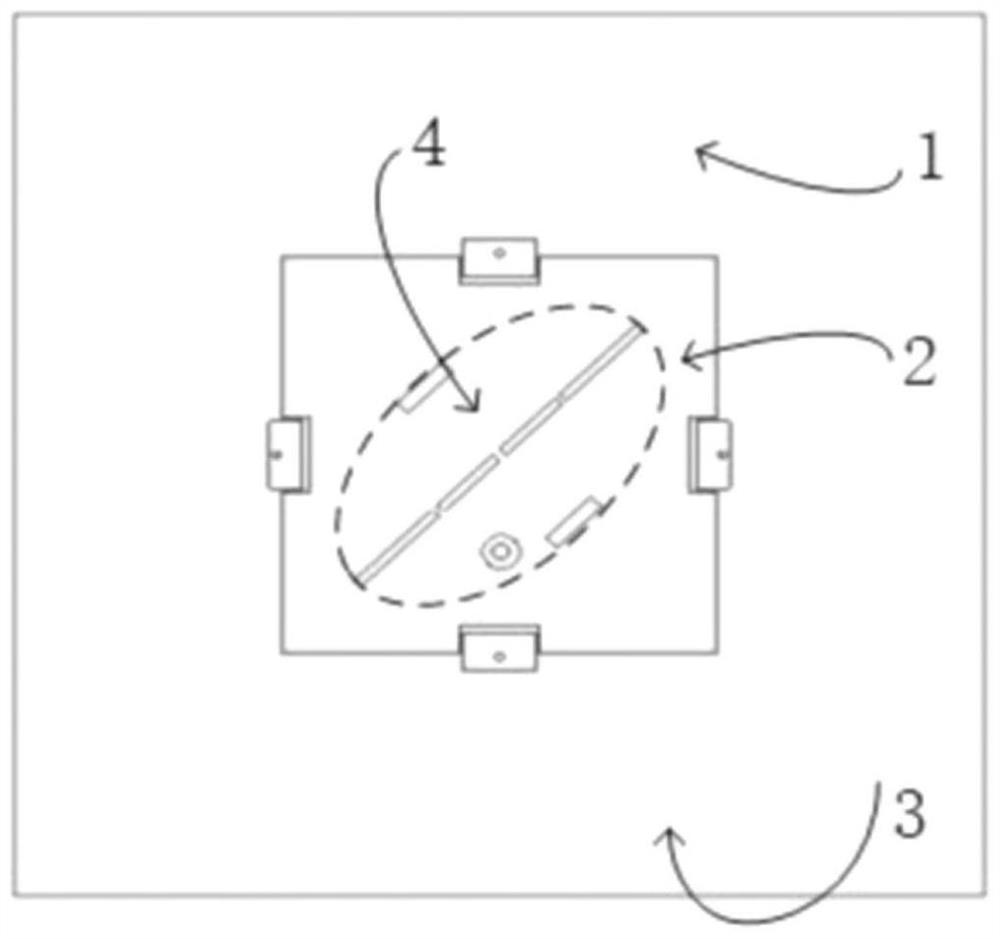
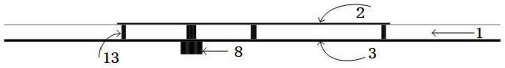
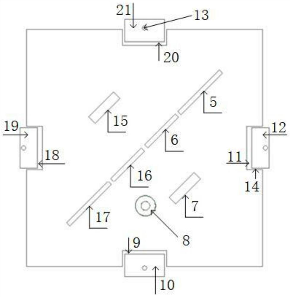
[0038] In this embodiment, as figure 1 Shown is a schematic plan view of the circularly polarized microstrip antenna structure of the low-profile high-gain wide-axis ratio beam in the present invention, which is characterized in that it includes a dielectric substrate 1, a radiation patch 2, a system floor 3 and a rectangu...


PUM


Abstract

The invention discloses a circularly polarized microstrip antenna with low profile, high gain and wide axial ratio beam. On the basis of a traditional microstrip patch antenna, a slot is formed in the diagonal direction of the surface of a radiation sheet, so that current on a patch flows along a slot edge, and the'path lengthening 'of the current is equivalent to inductance cascade connection, so that the resonant frequency of the antenna is reduced. Besides, parasitic capacitance of the gap and parasitic inductance of the via hole are introduced, can be equivalent to an LC circuit, and are used for adjusting double resonant frequency points excited by the antenna on a working frequency band, so that a 90-degree phase difference is ensured to be generated, the frequency ratio is reduced, and circularly polarized waves with wider axial ratio beams are obtained. In the aspect of the structure, the whole antenna is very symmetrical, some unnecessary coupling interference can be reduced, and then the 3-dB axial ratio beam symmetry of the antenna is optimized. In addition, the antenna is relatively simple in structure and remarkable in effect, and the method is easy to implement.

Description

technical field [0001] The invention belongs to the technical field of circularly polarized microstrip antennas, in particular to a circularly polarized microstrip antenna with low profile and high gain and wide-axis ratio, in particular to a circular polarized microstrip antenna that can realize low profile, high gain and wide-axis ratio in the WIFI frequency band Polarized Microstrip Antenna. Background technique [0002] With the rapid development of wireless communication technology, linearly polarized antennas are no longer enough to meet people's needs in various applications, which puts forward different requirements for the performance and form of antennas, and circularly polarized antennas rely on their unique With some polarization characteristics, it can receive electromagnetic waves of any polarization, and can also allow any polarization antenna to receive the radiation waves it emits, which plays an increasingly important role in many wireless applications. ...

Claims


Application Information

Patent Timeline
IPC IPC(8): H01Q1/38H01Q1/48H01Q1/50H01Q13/10
CPCH01Q1/38H01Q1/48H01Q1/50H01Q13/106Y02D30/70
Inventor 郑博文袁博王高峰
Owner HANGZHOU DIANZI UNIV
Why Eureka
Try Eureka