
Method for detecting initial position and rotating speed of rotor of permanent magnet synchronous motor at high rotating speed

A permanent magnet synchronous motor, rotor initial position technology, applied in the direction of electronic commutator, control generator, motor generator control, etc., can solve the problem of dependence, etc., achieve weakening influence, strong robustness and reliability, detection high precision effect

Active Publication Date: 2022-07-05
HARBIN INST OF TECH
View PDF5 Cites 0 Cited by
  • Summary
  • Abstract
  • Description
  • Claims
  • Application Information

AI Technical Summary

Problems solved by technology

[0005] Aiming at the problem that the traditional zero-voltage vector pulse method relies on motor parameters in the detection of the initial position and rotational speed of the rotor, the present invention provides a method for detecting the initial position and rotational speed of the rotor at high rotational speeds of permanent magnet synchronous motors

Method used


Image

  • Method for detecting initial position and rotating speed of rotor of permanent magnet synchronous motor at high rotating speed
  • Method for detecting initial position and rotating speed of rotor of permanent magnet synchronous motor at high rotating speed
  • Method for detecting initial position and rotating speed of rotor of permanent magnet synchronous motor at high rotating speed

Examples


specific Embodiment approach 1

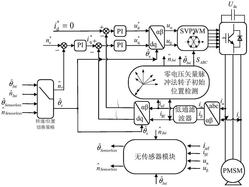
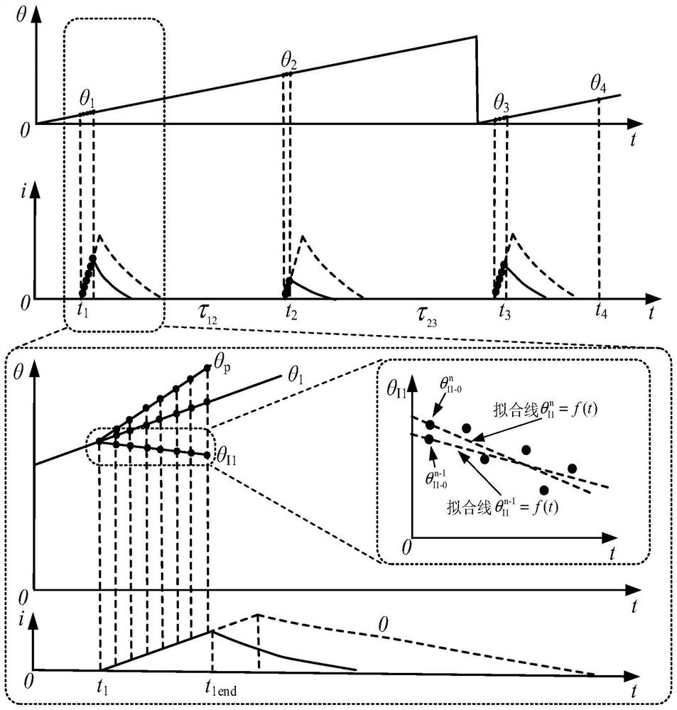
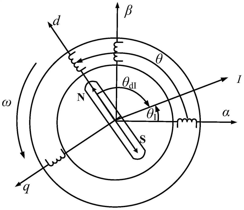
[0101] Specific implementation mode 1. Combination Figure 1 to Figure 7 As shown, the present invention provides a method for detecting the initial position and rotational speed of the rotor of a permanent magnet synchronous motor at a high rotational speed, which is characterized by comprising:

[0102] For the permanent magnet synchronous motor running at high speed, the mathematical model of the permanent magnet synchronous motor is designed; at the first selected time point t 1 , apply the first zero-voltage vector pulse to the mathematical model of the permanent magnet synchronous motor, and perform a current sampling in each PWM cycle during the application of the first zero-voltage vector pulse, and calculate the current vector according to the results of each current sampling. The current position angle in the coordinate system; perform linear fitting on the obtained current position angle to determine the zero current vector position angle θ at the zero point of the ...


PUM


Abstract

A rotor initial position and rotating speed detection method for a permanent magnet synchronous motor at a high rotating speed belongs to the technical field of motor control. The problem that a traditional zero-voltage vector pulse method depends on motor parameters in detection of the initial position and the rotating speed of a rotor is solved. Comprising the following steps: applying a first zero voltage vector pulse to a permanent magnet synchronous motor mathematical model, and calculating to obtain a rotor actual position angle at a first pulse zero point; applying a second zero voltage vector pulse at a second selected time point to obtain an actual position angle of the rotor at the zero point of the second pulse; further calculating to obtain a first-stage rotor rotating speed; similarly, the actual position angle of the rotor at the third pulse zero point is obtained; on this basis, the second-stage rotor speed is obtained; determining a rotor rotating speed at a selected switching time point according to the rotor rotating speeds in the first two stages; and the actual position angle of the rotor at the selected switching time point is determined according to the actual position angles of the rotor at the second pulse zero point and the third pulse zero point. The initial position and the rotating speed of the rotor can be obtained by separating motor parameters.

Description

technical field [0001] The invention relates to a method for detecting the initial position and rotational speed of a rotor of a permanent magnet synchronous motor at high rotational speed, and belongs to the technical field of motor control. Background technique [0002] With the continuous advancement of mechanization and electrification, motors play an increasingly important role in electromechanical energy conversion. Due to the advantages of simple structure, high power density, high efficiency, and good dynamic and static performance, permanent magnet synchronous motor has an ideal development prospect in the field of electrical transmission, especially in the field of medium and small power applications. [0003] The high-performance permanent magnet synchronous motor vector control system relies on high-precision rotor position detection to ensure the accuracy of coordinate transformation. The sensorless control technology can realize high-precision rotor position a...

Claims


Application Information

Patent Timeline
Patent Type & Authority Applications(China)
IPC IPC(8): H02P6/16H02P6/17H02P6/28H02P21/00H02P21/18H02P21/22H02P25/022H02P27/08
CPCH02P6/16H02P6/17H02P6/28H02P21/0003H02P21/18H02P21/22H02P25/022H02P27/08H02P2205/01H02P2205/07H02P2207/05
Inventor 张国强李润东王高林王奇维丁大尉徐殿国
Owner HARBIN INST OF TECH
Learn More