Refrigeration/heat pipe composite cabinet air conditioning system and control method thereof

A technology of cabinet air conditioning and control method, applied in the direction of cooling/ventilation/heating transformation, can solve the problems of complex system design, high material cost, many copper pipe branches, etc., and achieves reduced operating costs, simple pipelines, and energy consumption. reduced effect

Pending Publication Date: 2022-07-05
苏州黑盾环境股份有限公司
View PDF0 Cites 0 Cited by
  • Summary
  • Abstract
  • Description
  • Claims
  • Application Information

AI Technical Summary

Problems solved by technology

However, the general system design of the existing refrigeration and heat pipe composite air conditioners is complex, and there are many copper pipe branches. Most products require two separate sets of pipelines and heat exchangers for refrigeration and heat pipes, and the material cost is high.

Method used


Image

  • Refrigeration/heat pipe composite cabinet air conditioning system and control method thereof
  • Refrigeration/heat pipe composite cabinet air conditioning system and control method thereof
  • Refrigeration/heat pipe composite cabinet air conditioning system and control method thereof

Examples


Embodiment 1

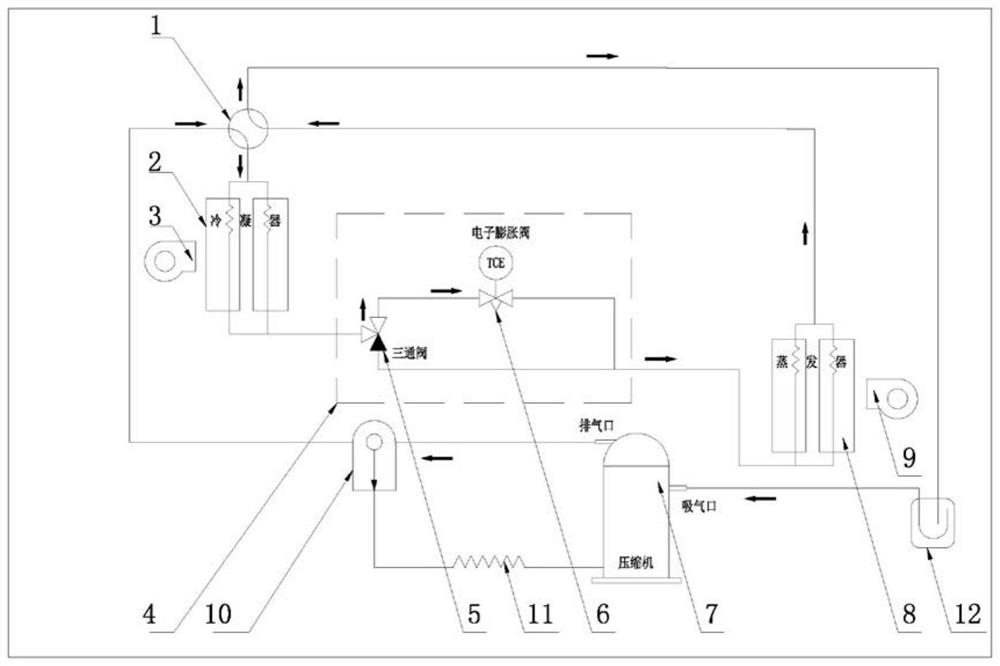
[0031] like Figure 1-5 shown, in the illustration, assembled from the following components:

[0032]

[0033]

[0034] Assembly instructions: Install the condenser 2, the external circulation fan 3, the throttle variable mechanism 4, the three-way valve 5, the electronic expansion valve 6, the compressor 7, the evaporator 8 and the inner circulation fan 9 inside the cabinet shell, and then Install the refrigeration system connecting pipeline, the controller and the four-way valve 1 inside the cabinet shell, and connect the refrigeration system connecting pipeline to the exhaust port of the compressor 7, the inlet of the condenser 2, and the evaporator 8 through the four-way valve 1 respectively. The outlet of the three-way valve 5 and the suction port of the compressor 7 are connected to the outlet of the condenser 2 through the pipeline, and one outlet of the three-way valve 5 is connected in series to the inlet of the evaporator 8 by the electronic expansion valve 6. ...

Embodiment 2

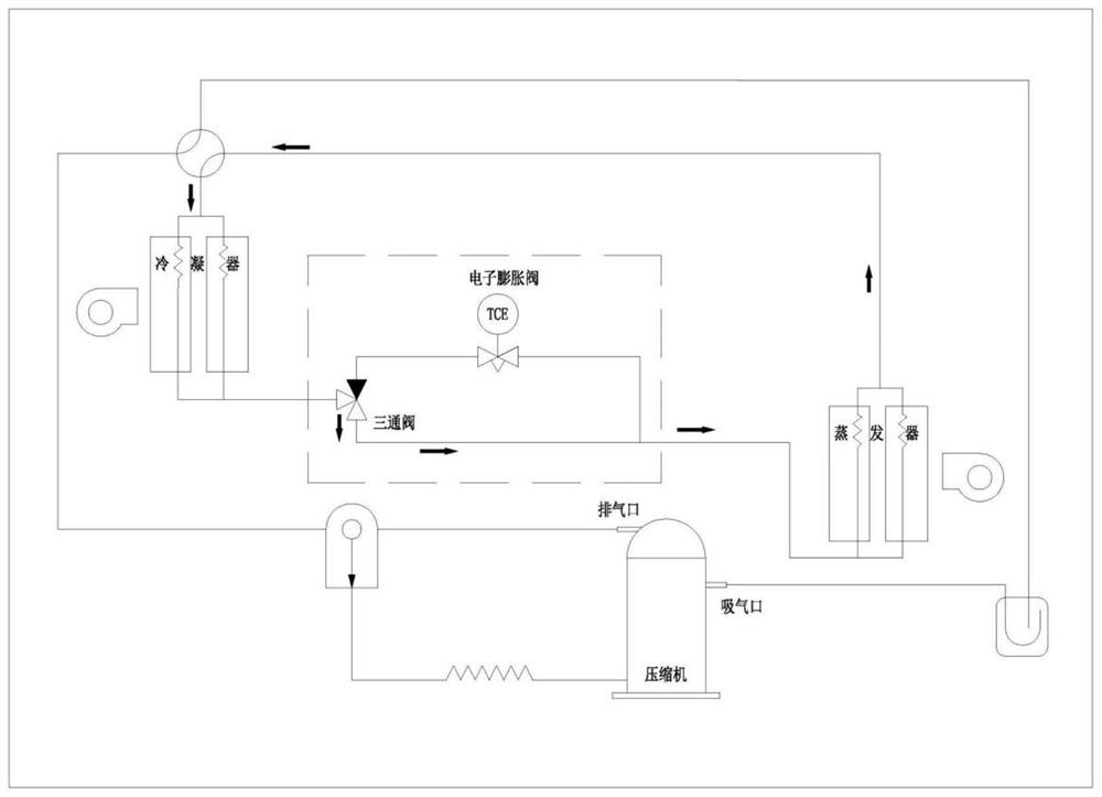
[0036] like Figure 1-5 shown, in the illustration, assembled from the following components:

[0037]

[0038]Assembly instructions: Install the condenser 2, the external circulation fan 3, the throttling variable mechanism 4, the compressor 7, the evaporator 8, the internal circulation fan 9, the oil separator 10 and the gas-liquid separator 12 inside the cabinet shell, and then Install the refrigeration system connecting pipeline, controller and four-way valve 1 inside the cabinet shell, and connect the refrigeration system connecting pipeline through the four-way valve 1 to the air outlet of the oil separator 10, the inlet of the condenser 2, and the evaporator 8 respectively. The outlet of the oil separator 10 and the inlet of the gas-liquid separator 12, the air outlet of the oil separator 10 and the exhaust port of the compressor 7 are connected by pipelines, the oil return port of the oil separator 10 and the compressor 7 are connected by the oil return capillary 11,...


PUM


Abstract

The invention relates to the technical field of cabinet temperature control equipment in the communication industry, the electric power industry and the industrial control industry, in particular to a refrigeration/heat pipe composite type cabinet air conditioning system and a control method thereof.The refrigeration/heat pipe composite type cabinet air conditioning system comprises a cabinet shell, and a condenser, an outer circulation fan, a compressor, an evaporator, an inner circulation fan and a throttling variable mechanism are arranged in the cabinet shell; the throttling variable mechanism comprises a three-way valve and an electronic expansion valve. Through the automatic control system, automatic operation of the heat pipe system and the steam compression refrigeration system is realized according to different working conditions, so that the system always operates in energy-saving modes under different working conditions, the temperature in the cabinet is ensured to be in a reasonable range, the operation cost of the system is reduced, the energy consumption is reduced, and the annual comprehensive energy efficiency ratio is improved. In addition, the composite cabinet air conditioner is reasonable in structural design and simple in pipeline, and material cost is saved; intelligent automatic control operation is achieved, and operation and maintenance are convenient.

Description

technical field [0001] The invention relates to cabinet temperature control equipment in communication, electric power and industrial control industries. In particular, it relates to a refrigeration / heat pipe composite type cabinet air conditioning system and a control method thereof. Background technique [0002] Cabinet air conditioners are widely used in outdoor communication cabinets, base stations, battery cabinets, charging piles, industrial electrical control cabinets and other industries. At present, cabinet air conditioners used in domestic and foreign industries are mainly composed of cabinet shells, compressors, internal circulation fans, and external circulation fans. , condenser, evaporator, middle partition, refrigeration system connecting pipeline and control part. Its working principle: After the air conditioner is powered on, the low-pressure vapor of the refrigerant in the refrigeration system is inhaled by the compressor and compressed into high-pressure ...

Claims


Application Information

Patent Timeline
Patent Type & Authority Applications(China)
IPC IPC(8): H05K7/20
CPCH05K7/2059H05K7/206H05K7/2069H05K7/20745H05K7/20754H05K7/20827H05K7/20136H05K7/20145H05K7/202H05K7/20309H05K7/20318H05K7/20327H05K7/20336H05K7/207H05K7/20836
Inventor 李骏郭世良都文星张伟曾凯
Owner 苏州黑盾环境股份有限公司
Why Eureka
Try Eureka