Left auricle plugging device

A technology of occluder and occluder disc, which is applied in the field of medical devices, can solve problems such as easy puncture of the heart, stuck on the edge of the sheath tube wall, and poor fatigue strength, so as to improve safe use efficiency, reduce blood vessel damage, Excellent fatigue resistance effect

Pending Publication Date: 2022-07-08
SHENZHEN KYD BIOMEDICAL TECH CO LTD
View PDF7 Cites 0 Cited by
  • Summary
  • Abstract
  • Description
  • Claims
  • Application Information

AI Technical Summary

Problems solved by technology

However, the anchoring thorns piercing the left atrium are repeatedly positioned, and when the occluder is recovered, it will be stuck on the edge of the sheath wall, making the occluder unable to be recovered, and repeated positioning
Moreover, the fixed plate of this hybrid left atrial appendage occluder usually deforms greatly to reverse the direction of the anchoring spines, causing the tension and deformation of the fixed plate to reach the limit value of the material
This device has poor fatigue strength in permanent implantation, and is prone to breakage, puncturing other tissues such as the heart, and endangering life
[0013] In addition, CN104352261A discloses a left atrial appendage occluder with an improved structure. The connecting plate provides support for the anchoring plate to form a rigid structure, so that the deformation is large and the processing is difficult. In addition, the planar structure of the anchoring plate is stable during the opening and recovery process. If it is larger than the diameter of the anchoring disc, it is easy to puncture other tissues such as the heart and endanger life. The schematic diagram of its opening is as follows Figure 11 shown

Method used


Image

  • Left auricle plugging device
  • Left auricle plugging device
  • Left auricle plugging device

Examples


Embodiment 1

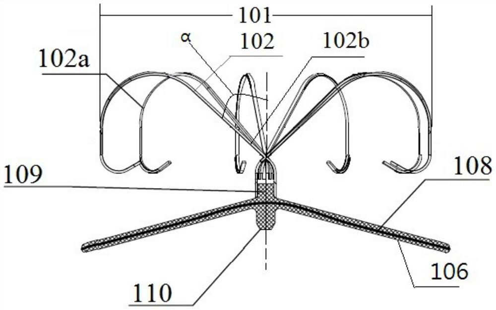
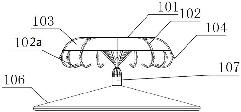
[0058] like figure 1 A left atrial appendage occluder, comprising a blocking disc 106 and an anchoring disc 101 connected with the blocking disc,

[0059] The plugging disc has a net-like structure with a flow blocking film 108 arranged inside. The distal end of the plugging disc is fixed with a tubular member 109, and the other end of the plugging disc is connected to the anchoring disc through the tubular member. The proximal end of the disc is fixed with a plug 110 and is provided with a structure for connecting with the delivery device;

[0060] The other end of the tubular member relative to the fixed blocking disk is provided with a plurality of support rods 102, the support rods are issued from a direction relative to the blocking disk, and the proximal end 102b of the support rod spans the center of the tubular member to the opposite side. The support rods are arranged in a cross radial pattern to form the anchoring disc 101. The angle α between the proximal end 102b...

Embodiment 2

[0062] like figure 1 A left atrial appendage occluder, comprising a blocking disc 106 and an anchoring disc 101 connected with the blocking disc,

[0063] The plugging disc has a net-like structure with a flow blocking film 108 arranged inside. The distal end of the plugging disc is fixed with a tubular member 109, and the other end of the plugging disc is connected to the anchoring disc through the tubular member. The proximal end of the disc is fixed with a plug 110 and is provided with a structure for connecting with the delivery device;

[0064] The other end of the tubular member relative to the fixed blocking disk is provided with a plurality of support rods 102, the support rods are issued from a direction relative to the blocking disk, and the proximal end 102b of the support rod spans the center of the tubular member to the opposite side. The support rods are arranged in a cross radial pattern to form the anchoring disc 101. The angle α between the proximal end 102b...

Embodiment 3

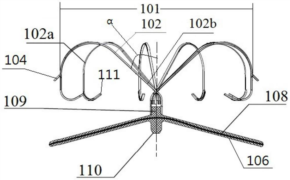
[0067] like figure 2 A left atrial appendage occluder, comprising a blocking disc 106 and an anchoring disc 101 connected with the blocking disc,

[0068] The plugging disc has a net-like structure with a flow blocking film 108 arranged inside. The distal end of the plugging disc is fixed with a tubular member 109, and the other end of the plugging disc is connected to the anchoring disc through the tubular member. The proximal end of the disc is fixed with a plug 110 and is provided with a structure for connecting with the delivery device;

[0069] The other end of the tubular member relative to the fixed blocking disk is provided with a plurality of support rods 102, the support rods are issued from a direction relative to the blocking disk, and the proximal end 102b of the support rod spans the center of the tubular member to the opposite side. The support rods are arranged in a cross radial pattern to form the anchoring disc 101. The angle α between the proximal end 102b...


PUM

PropertyMeasurementUnit
heightaaaaaaaaaa
heightaaaaaaaaaa
heightaaaaaaaaaa

Abstract

The invention provides a left atrial appendage occluder which comprises an occluding disc and an anchoring disc connected with the occluding disc, the occluding disc is of a net structure, a flow blocking film is arranged in the occluding disc, and the far end of the occluding disc is fixed through a tubular component; a plurality of supporting rods are arranged at the other end, opposite to the fixed plugging disc, of the tubular component, the supporting rods extend from the direction opposite to the plugging disc, the near ends of the supporting rods span the center of the tubular component to the opposite side, and the supporting rods are arranged in a crossed radial mode to form an anchoring disc; an included angle of a specific angle is formed between the near end of the supporting rod and the central axis of the tubular component. In addition, the preferable scheme comprises a modified flow blocking membrane, so that the biocompatibility is improved, endothelialization is rapid, and thrombosis is reduced. The left auricle plugging device is good in effect of blocking thrombus in a left auricle from flowing out, capable of being repeatedly positioned, stable in fixation and good in fatigue resistance.

Description

[0001] This application is a divisional application of the original Chinese invention patent application CN201680072308.4. The application date of the original application is December 26, 2016, and the name of the invention-creation of the original application is "left atrial appendage occluder". [0002] The original application is an invention patent application entered into China's national phase based on the international application PCT / CN2016 / 112062 with an application date of December 26, 2016 under the Patent Cooperation Treaty. [0003] The international application, the original application and the present application all claim the priority of the following patent applications: [0004] A Chinese invention patent application entitled "Left atrial appendage occluder" with application number CN201511003714.9, filed on December 29, 2015; and [0005] The Chinese invention patent application named "Left atrial appendage occluder" and the application number is CN20161011916...

Claims


Application Information

Patent Timeline
Patent Type & Authority Applications(China)
IPC IPC(8): A61B17/12
CPCA61B17/12122A61B17/12031A61B17/12177A61B2017/00796A61B17/0057A61B17/12172A61B2017/00575A61B2017/00579A61B2017/00592A61B2017/00597A61B2017/00615A61B2017/00938A61L31/06A61L31/14A61L2400/18C08L67/02A61B17/12A61F2/00A61B17/12145
Inventor 陈奕龙黄伟
Owner SHENZHEN KYD BIOMEDICAL TECH CO LTD
Why Eureka
Try Eureka