Stainless steel workpiece cutting device

A cutting device, stainless steel technology, applied in the direction of metal processing machinery parts, manufacturing tools, metal processing equipment, etc., can solve the problems of cutting device damage, stainless steel splash, single structure, etc., to prevent clogging, prevent excessive accumulation of debris, It is convenient for the saving effect of the energy

Inactive Publication Date: 2022-07-08
JIANGSU MINGLUSINLESS STEEL
View PDF8 Cites 0 Cited by
  • Summary
  • Abstract
  • Description
  • Claims
  • Application Information

AI Technical Summary

Problems solved by technology

Relevant parts have extremely high requirements on the processing surface quality and processing accuracy, and the appearance is required to be clean and smooth, without burrs and cracks, so as to ensure the good appearance of 3C parts, high corrosion resistance and high biological safety of medical surgical instruments. In order to meet the inspection requirements of industry standards, for the existing stainless steel cutting devices, many of the cutting devices have a relatively simple structure. During the process of cutting stainless steel, stainless steel debris will be splashed everywhere, which may hurt people. , the cutting device does not have a device to collect debris, so that the debris generated by cutting gradually increases, and finally leads to damage to the cutting device

Method used


Image

  • Stainless steel workpiece cutting device
  • Stainless steel workpiece cutting device
  • Stainless steel workpiece cutting device

Examples


Embodiment Construction

[0027] The technical solutions in the embodiments of the present invention will be clearly and completely described below with reference to the accompanying drawings in the embodiments of the present invention. Obviously, the described embodiments are only a part of the embodiments of the present invention, but not all of the embodiments. Based on the embodiments of the present invention, all other embodiments obtained by those of ordinary skill in the art without creative efforts shall fall within the protection scope of the present invention.

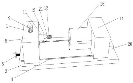
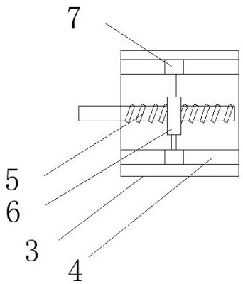
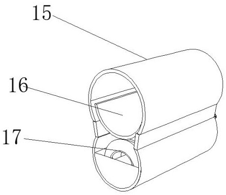
[0028] see Figure 1-5 , a stainless steel workpiece cutting device, including a tool device 1 and a collection device 2, the bottom end of the tool device 1 is provided with a base 3, the upper end of the base 3 is provided with two chute 4, the side end of the base 3 is located in two sliding A threaded rod 5 is movably inserted in the middle of the groove 4, and a threaded block 6 is movably sleeved on the threaded rod 5, and the t...


PUM


Abstract

The invention relates to the technical field of cutting, and discloses a stainless steel workpiece cutting device which comprises cutter equipment and a collecting device, two semi-arc cylinders are inserted into a resisting box, a sliding cover is arranged on the inner wall of the upper semi-arc cylinder, a clamping seat is arranged in the upper semi-arc cylinder, a pushing rod is movably inserted into the lower semi-arc cylinder, and a clamping groove is formed in the pushing rod. A gear is fixedly connected to the end, located in the resisting box, of the pushing rod, the gear rod is movably connected to the interior of the resisting box, a sliding groove is formed in the side end of the resisting box, the side end of the sliding cover is fixedly connected with a rotating shaft gear, and the gear on the pushing rod and the rotating shaft gear on the sliding cover are meshed together through the gear rod. According to the cutting device, chippings are prevented from splashing, people are prevented from being injured, chippings on the inner wall are cleaned, excessive chippings are prevented from being accumulated, and mechanical faults are avoided, so that the integrity and integration of the device are embodied, the device can save energy conveniently, and the utilization rate of energy conversion is high.

Description

technical field [0001] The invention relates to the technical field of cutting, in particular to a stainless steel workpiece cutting device. Background technique [0002] High-strength and high-toughness stainless steel has the characteristics of good mechanical properties, high corrosion resistance and excellent biocompatibility. The relevant parts have extremely high requirements on the surface quality and processing accuracy, and the appearance is required to be clean and smooth, and there should be no burrs and cracks, so as to ensure the good appearance of the 3C parts and components, and ensure the high corrosion resistance and high biological safety of medical and surgical instruments. In order to meet the inspection requirements of industry standards, for the existing stainless steel cutting devices, many cutting devices have a relatively simple structure. In the process of cutting stainless steel, stainless steel chips will splash everywhere, which may injure people...

Claims


Application Information

Patent Timeline
Patent Type & Authority Applications(China)
IPC IPC(8): B23Q11/00B23Q11/08
CPCB23Q11/0042B23Q11/08Y02P70/10
Inventor 马爱明陈守荣
Owner JIANGSU MINGLUSINLESS STEEL
Why Eureka
Try Eureka