Combined system floor system and construction method thereof

A construction method and system technology, which can be applied in the treatment of floors, building materials, structural elements, etc., can solve problems such as water leakage, and achieve the effect of suppressing floor cracks, avoiding hidden dangers of water seepage, and effectively bearing loads.

Active Publication Date: 2022-07-08
CHINA RAILWAY CONSTR ENG GROUP
View PDF6 Cites 0 Cited by
  • Summary
  • Abstract
  • Description
  • Claims
  • Application Information

AI Technical Summary

Problems solved by technology

However, engineering examples in recent years have shown that as the span of the building structure increases, the deflection of the BDF hollow floor slab gradually increases, resulting in cracks in the hollow floor slab, which will lead to water leakage and other phenomena.

Method used


Image

  • Combined system floor system and construction method thereof
  • Combined system floor system and construction method thereof
  • Combined system floor system and construction method thereof

Examples


Embodiment 1

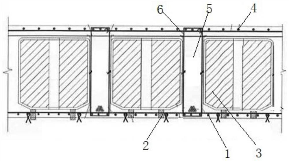
[0043] In order to solve the above problems, the present embodiment discloses a combined system floor, including: bottom steel bars 1 , stirrup steel bars 2 , box body members 3 and upper-layer steel bars 4 . Among them, the actual number of base steel bars 1, stirrup steel bars 2, box members 3 and upper steel bars 4 is determined according to the project requirements.

[0044] like figure 1 As shown in the figure, the bottom steel bar 1 is laid in the formwork as required; the stirrup steel bar 2 is arranged on the bottom plate steel bar 1. The box member 3 is laid on the stirrup steel bar 2 according to the engineering drawing. When laying the box member 3, it is necessary to handle it with care, and lay it in strict accordance with the detailed drawings. In the specific operation, it is recommended to first pull the wires to complete the arrangement of a row of boxes in the vertical and horizontal directions, and then align the left and right sides of the remaining boxes ...

Embodiment 2

[0057] Based on the above-described embodiment, the present embodiment discloses a construction method of a combined system floor, specifically comprising the following steps:

[0058] In order to effectively control the floating of the BDF box during the concrete pouring process, the anti-floating iron wire should be fixed after the steel bars on the bottom plate are laid and bound and the protective layer cushions are placed. Combined with the box size of this project, 12# iron wire should be used to fasten the intersection of the steel bars on the bottom plate with a spacing of no more than 600mm, and then anchor it on the supporting steel pipe, wooden square or formwork after passing through the bottom plate formwork.

[0059] After the square stool is placed, the box is laid out according to the layout plan. In the process of laying the box, it should be handled with care, and laid in strict accordance with the detailed drawings. In the specific operation, it is recommen...


PUM


Abstract

The invention discloses a combined system floor system and a construction method thereof, and belongs to the technical field of constructional engineering. According to the structure, a box body component is provided with an inter-ribbed beam, a plurality of sets of prestressed tendon components of a square structure are vertically arranged in the inter-ribbed beam, and upper-layer steel bars and bottom plate steel bars located over and under the prestressed tendon components penetrate through the prestressed steel bars. The prestressed rib components are additionally arranged in the rib beams of the box body components, so that the net-shaped rib beam structure with the I-shaped section in the floor can bear loads more effectively, and the performance of the floor is improved. The prestressing technology and the BDF hollow floor slab technology are combined, the advantages of the prestressing technology are fully exerted, the deflection of the BDF hollow floor slab is reduced, floor slab cracks are restrained, and the hidden danger of water seepage is avoided.

Description

technical field [0001] The invention belongs to the technical field of construction engineering, and particularly relates to a combined system floor and a construction method thereof. Background technique [0002] With the continuous advancement of urbanization, buildings are gradually developing in the direction of super-large span and super-large space. Ordinary reinforced concrete cast-in-place floor slabs can no longer meet this structural form. Therefore, BDF hollow core slab technology came into being, and has mature. However, engineering examples in recent years have shown that as the span of the building structure becomes larger and larger, the deflection of the BDF hollow floor slab gradually increases, resulting in cracks in the hollow core floor, which will lead to water leakage and other phenomena. SUMMARY OF THE INVENTION [0003] In order to solve the technical problems existing in the above background technology, the present invention provides a combined sy...

Claims


Application Information

Patent Timeline
Patent Type & Authority Applications(China)
IPC IPC(8): E04B5/32E04C5/08E04G21/12
CPCE04B5/32E04B5/326E04C5/08E04G21/121
Inventor 钱少波陆剑峰孙泽昌芮兴龙李超郑奎智张健马伟周华嵘吴建录程军苟恒
Owner CHINA RAILWAY CONSTR ENG GROUP
Why Eureka
Try Eureka