Circulating flow air guide device

A technology of air guiding device and circulating flow, which is applied in the direction of dry gas arrangement, lighting and heating equipment, dryer, etc., which can solve the problem of difficult dust removal of dust and achieve the effect of reducing power consumption

Pending Publication Date: 2022-07-08
MENGZHOU YUANHONG DRYING EQUIP RES & DEV CO LTD
View PDF0 Cites 0 Cited by
  • Summary
  • Abstract
  • Description
  • Claims
  • Application Information

AI Technical Summary

Problems solved by technology

The dust in the humidity in the drum silo is not easy to remove

Method used


Image

  • Circulating flow air guide device
  • Circulating flow air guide device
  • Circulating flow air guide device

Examples


Embodiment 1

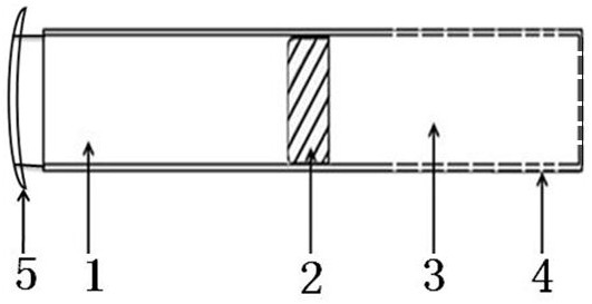
[0036] like figure 1 , figure 2 , image 3 The shown circulating flow air guide device includes an air guide pipe 1, a fan 2, a filter cartridge 3, a guide plate 5, and a bracket.

[0037] The length of the airway 1 is 2000mm, and the diameter is 400mm. The nozzle at the end of the air duct 1 where the fan 2 is installed is the air inlet, and the other end is the exhaust port.

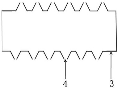
[0038] The filter cartridge 3 is a pipe with one end open and one end closed. The open end of the filter cartridge 3 connected to the fan 2 is an exhaust port; the length of the filter cartridge 3 is 3000mm and the diameter is 400mm. There are ventilation holes 4 on the cylinder body of the filter cartridge 3; the distance between the cone-shaped ventilation holes 4 and the adjacent cone-shaped ventilation holes 4 is 0.5 mm; the diameter of the cone-shaped ventilation holes 4 is 0.1 mm.

[0039]The fan 2 is installed in the pipe of the air duct 1 , and the exhaust port end of the filter cartridge ...

Embodiment 2

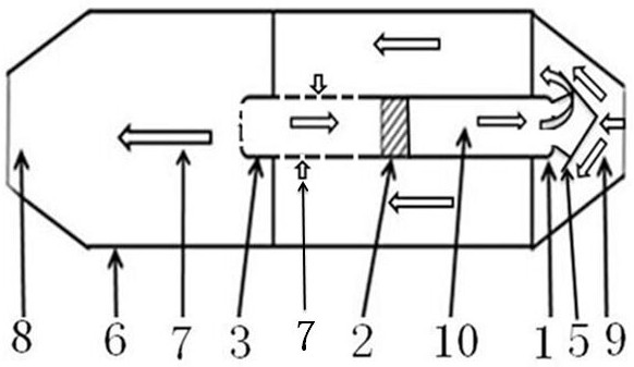
[0052] like figure 1 , Figure 4 The shown circulating air guide device includes an air guide pipe 1 , a fan 2 , a filter cartridge 3 , a guide plate 5 , a bracket, and a guide plate 11 .

[0053] The structure of the circulating flow air guide device of the second embodiment is the same as that of the circulating flow air guide device introduced in the first embodiment, and will not be repeated.

[0054] The filter cartridge 3 is a pipe material with open ends at both ends; the nozzle of the filter cartridge 3 connected to the end of the fan 2 is an exhaust port, and the other end is an air inlet.

[0055] The fan 2 is fixed on the air inlet of the air duct 1 , and the exhaust port end of the filter cartridge 3 is fixed on the fan 2 .

[0056] The outer diameter of the guide plate 5 is 80mm larger than the diameter of the air guide pipe, the outer diameter of the guide plate 11 is 150mm larger than that of the filter cartridge 3, the outside diameter of the guide plate 5 is...


PUM


Abstract

The circulating flow air guide device comprises an air guide pipe, a fan, a filter cartridge, a flow guide plate and a drainage plate. The heat-conducting medium is subjected to circulating convection in the roller bin, the filter cartridge and the air guide pipe under the pumping and discharging action of the fan; the guide plate arranged outside the exhaust port of the air guide pipe guides and shunts the heat-conducting medium entering from the discharge port of the roller bin, so that the heat-conducting medium entering from the discharge port of the roller bin and the heat-conducting medium discharged from the air guide pipe are prevented from causing countercurrent conflict, and the power consumption of the fan is increased. Materials in the roller bin fly up and down along with the lifting plate, and the falling materials rub and move to take away dust on the air holes, so that the dust removal effect on the air holes is achieved. The heat-conducting medium is circularly convected and repeatedly utilized in the drying section of the roller bin through the circular flow air guide device, the retention time of the heat-conducting medium in the roller bin is prolonged through the circular flow air guide device, and the effective utilization rate of heat energy of the heat-conducting medium is increased.

Description

technical field [0001] The invention relates to an air guide device matching drying equipment, in particular to a circulating flow air guide device. Background technique [0002] During the drying process of the drum chamber of the drying equipment, the hot air as the heat transfer medium enters from one end of the drum chamber, passes through the interior of the drum chamber, and finally is discharged from the other end of the drum chamber. When the time is short, the effective utilization rate of the thermal energy carried by the heat transfer medium is greatly reduced. Dust in the moisture in the drum bin is not easy to remove. [0003] Therefore, it is now necessary to design a circulating flow air guide device, which can handle the dust in the wet air well, and use the circulating flow air guide device to increase the retention and drying time of the heat transfer medium in the drum silo, and improve the heat energy of the hot air. effective drying rate. SUMMARY OF ...

Claims


Application Information

Patent Timeline
Patent Type & Authority Applications(China)
IPC IPC(8): F26B21/00F26B21/02
CPCF26B21/004F26B21/003F26B21/02Y02P70/10
Inventor 程长青
Owner MENGZHOU YUANHONG DRYING EQUIP RES & DEV CO LTD
Why Eureka
Try Eureka