Sealed flue swivel joint and method

A rotary joint and sealed technology, applied in the field of metallurgical equipment, can solve the problems of endangering the health of environmental operators, increasing the load of the dust removal system, and diffuse, etc., achieving good fixing effect, increasing the temperature of exhaust gas, and eliminating dioxins

Active Publication Date: 2022-07-08
CHINA NAT HEAVY MACHINERY RES INSTCO
View PDF5 Cites 0 Cited by
  • Summary
  • Abstract
  • Description
  • Claims
  • Application Information

AI Technical Summary

Problems solved by technology

[0003] At present, because the known electric furnace does not have the function of scrap steel preheating, the dust removal pipeline is arranged on the water-cooled furnace cover, which can rotate with the water-cooled furnace cover, but the fixed side of the flue and There are gaps between the flues on the furnace cover. During smelting, outside air will be sucked into the flues, which increases the load on the dust removal system. When the tapping furnace body is tilted to tap steel, the water-cooled furnace cover must first rotate to one side. , so that the flue will be disconnected due to the rotation of the furnace cover during tapping, which will cause the flue gas to permeate the workshop during tapping, endangering the environment and the health of operators

Method used


Image

  • Sealed flue swivel joint and method

Examples


Embodiment 1

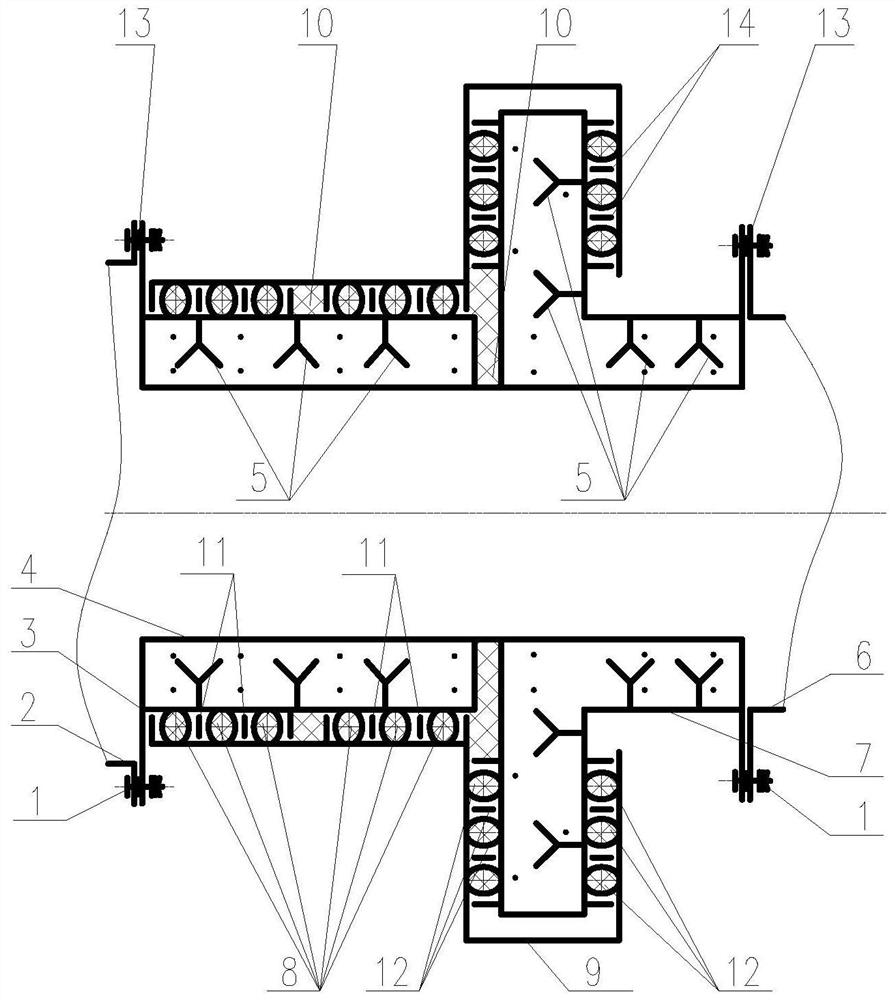
[0035] refer to figure 1 A sealed flue flue rotary joint shown includes a rotary flange 3, a fixed flange 7 and a floating cover 9; the rotary flange 3 is butted with the fixed flange 7, and a sealing packing is provided on the joint surface 10; the floating cover 9 is sleeved on the outer side wall of the rotary flange 3 and the connecting end of the fixed flange 7 and the rotary flange 3; a second sealing mechanism is arranged between the floating cover 9 and the fixed flange 7; the floating cover A first sealing mechanism is arranged along the circumferential direction between 9 and the rotary flange 3 .

[0036] In actual use, the sealed flue rotary joint is connected between the flue 2 on the rotary side of the electric furnace and the fixed flue 6 . When in use, firstly connect the rotary side flue 2 and the rotary flange 3 of the electric furnace detachably through the bolt group 1, and install a gasket 13 on the joint surface of the rotary side flue 2 of the electric ...

Embodiment 2

[0038] refer to figure 1 A sealed flue flue rotary joint shown, on the basis of Embodiment 1, the first sealing mechanism includes a plurality of first sealing rings 8 and a plurality of first floating baffle rings 11; The first sealing ring 8 and the plurality of first floating baffle rings 11 are arranged at intervals; the gap between the first sealing ring 8 and the plurality of first floating baffle rings 11 is provided with a sealing packing 10 .

[0039] In actual use, the function of setting the first floating baffle ring 11 is to make the multiple first sealing rings 8 change according to the actual position, and automatically adjust the compression amount of each first sealing ring 8 to be approximately equal, so as to obtain a good seal At the same time, damage caused by mutual friction between adjacent first sealing rings 8 is avoided.

[0040] In the specific application, the specific floating adjustment process of the first floating baffle ring 11 is as follows: ...

Embodiment 3

[0047] refer to figure 1 In the illustrated sealed flue flue rotary joint, on the basis of Embodiment 1, the second sealing mechanism includes a plurality of second sealing rings 12 and a plurality of second floating baffle rings 14; The second sealing ring 12 is spaced apart from the plurality of second floating baffle rings 14 .

[0048] In actual use, the function of setting the second floating baffle ring 14 is to enable the position of the second sealing ring 12 to be adjusted according to the actual floating position. The specific adjustment process is as follows: when the furnace body tilts, the rotary flange 3 is driven to rotate, and the change of the central axis of the rotary flange 3 drives the floating cover 9 to slide along the outer side wall of the fixed flange 7, so that the relative position of the second sealing ring 12 occurs. Variation, under the floating action of the second floating baffle ring 14, the plurality of second sealing rings 12 disposed on th...


PUM


Abstract

The invention belongs to the technical field of metallurgical equipment, and particularly relates to a sealed flue swivel joint and a method. A rotary flange, a fixed flange and a floating cover form a sealed flue rotary joint; the rotary flange is in butt joint with the fixed flange, and sealing filler is arranged on a joint surface; the floating cover is sleeved on the outer side wall of the rotary flange and the connecting end of the fixed flange and the rotary flange; a second sealing mechanism is arranged between the floating cover and the fixed flange; a first sealing mechanism is arranged between the floating cover and the rotary flange in the circumferential direction. When the furnace body tilts, the rotary flange rotates at the same time and drives the floating cover to slide in the radial direction of the outer side face of the fixed flange, the influence caused by flue installation errors is eliminated, the dust removal flue is always in a sealed state, air sucked into the flue is reduced, the load of a dust removal system is effectively reduced, and the service life of the dust removal system is prolonged. And during secondary combustion, the temperature of the waste gas can be quickly increased to eliminate dioxin, so that the harm to the environment and personnel due to smoke leakage in the smelting process is avoided.

Description

technical field [0001] The invention belongs to the technical field of metallurgical equipment, and in particular relates to a sealed flue flue rotary joint and a method. Background technique [0002] In the electric furnace steelmaking, the upper body of the furnace body is provided with a dust removal flue, and the high temperature waste gas generated during the electric furnace steelmaking is drawn away and enters the dust removal system. [0003] At present, since the known electric furnace has no scrap preheating function, the dust removal pipe is arranged on the water-cooled furnace cover and can be rotated with the water-cooled furnace cover, but there is a gap between the fixed side of the flue and the flue on the furnace cover. During smelting, Outside air will be sucked into the flue, which increases the load of the dust removal system. When the tapping furnace body is tilted and tapped, the water-cooled furnace cover must be rotated to one side first, so that the ...

Claims


Application Information

Patent Timeline
Patent Type & Authority Applications(China)
IPC IPC(8): F27D17/00C21C5/40
CPCF27D17/002C21C5/40Y02P10/20
Inventor 赵腾吴建龙曹海玲朱浪涛刘蒙
Owner CHINA NAT HEAVY MACHINERY RES INSTCO
Why Eureka
Try Eureka