Calculation method for energy flow and carbon flow distribution of integrated energy system

A technology of integrated energy system and calculation method, applied in the calculation field of energy flow and carbon flow distribution of integrated energy system

Pending Publication Date: 2022-07-08
SOUTHEAST UNIV
View PDF0 Cites 3 Cited by
  • Summary
  • Abstract
  • Description
  • Claims
  • Application Information

AI Technical Summary

Problems solved by technology

Secondly, in the context of low carbon, there is a certain contradiction between the economic operation of the system and the reduction of carbon emissions

Method used


Image

  • Calculation method for energy flow and carbon flow distribution of integrated energy system
  • Calculation method for energy flow and carbon flow distribution of integrated energy system
  • Calculation method for energy flow and carbon flow distribution of integrated energy system

Examples


Embodiment 1

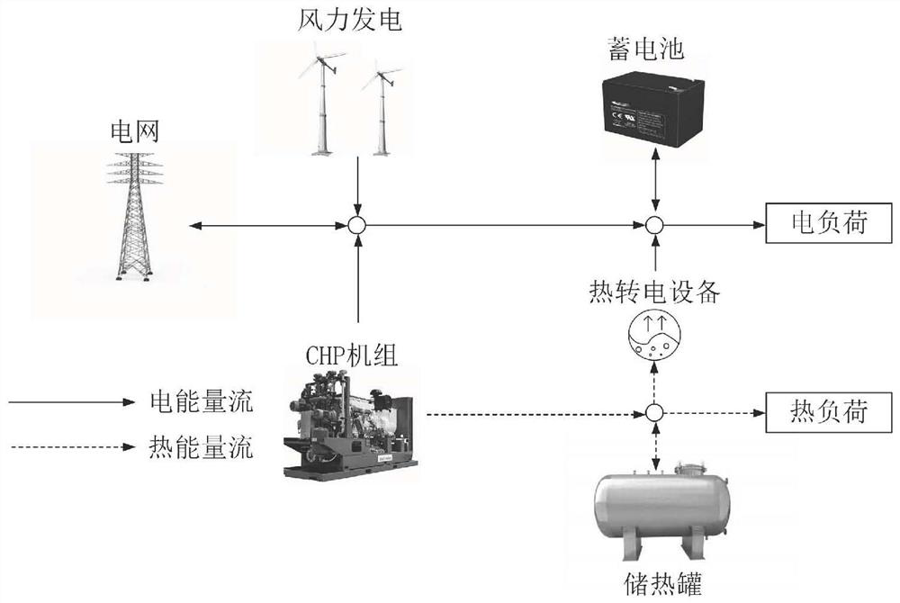
[0092] This embodiment is applied to an integrated energy system, the structure of the integrated energy system is as follows figure 1 shown.

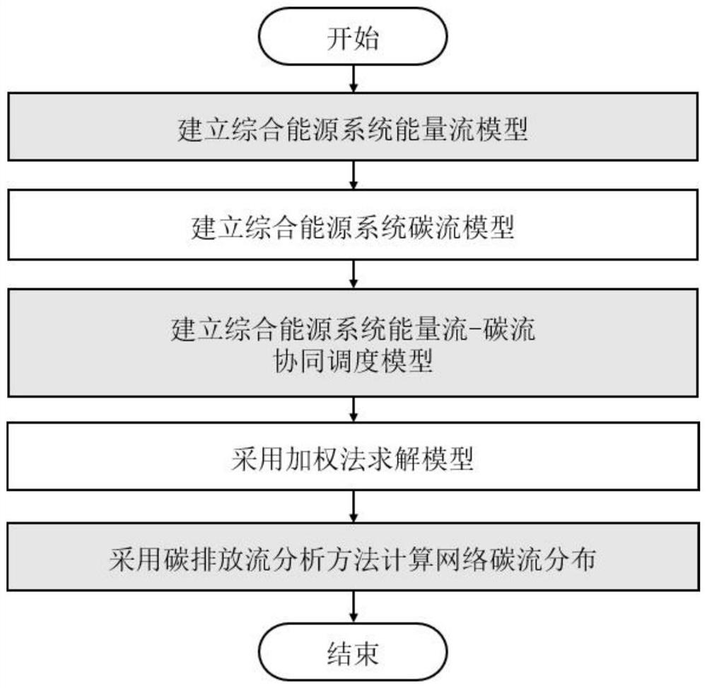
[0093] An energy flow-carbon flow co-optimization and carbon distribution calculation method for an integrated energy system based on carbon flow theory, such as figure 2 shown, including the following steps:

[0094] S1. Establish an energy flow model of an integrated energy system:

[0095] S11. Establish the objective function of the cost of the integrated energy system:

[0096] S111. Electricity purchase cost C grid :

[0097]

[0098] in, are the electricity purchase and sale prices of IES at time t, respectively; P t buy , P t sell are the electricity purchased and sold by the IES at time t, respectively.

[0099] S112. Equipment maintenance cost C m :

[0100]

[0101] Among them, i represents fan, cogeneration unit and electric boiler equipment; j represents battery and heat storage tank equipment; m i and m...

Embodiment 2

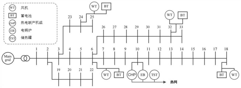
[0211] The multi-energy flow system of this embodiment consists of a 33-node power distribution system and a 51-node heating system, such as image 3 As shown, the system includes a 4MW cogeneration unit, a 2MW electric boiler, and four fans with a rated power of 1MW. The optimization period is 24h, the scheduling time interval is 1h, and the upper and lower limits of the indoor temperature of the building are respectively set to 27 ℃ and 17℃, the weights before the cost objective function and the carbon emission objective function in the weighting method are set to 0.5 and 0.5, respectively.

[0212] According to the steps of the present invention, the economic and low-carbon coordinated optimization of the integrated energy system is carried out. When the integrated energy system is running, the carbon potential of load nodes in different time periods is as follows: Figure 4 As shown, the integrated energy system source node 10 generates electricity and heats the carbon flo...


PUM


Abstract

The invention discloses a calculation method for energy flow and carbon flow distribution of an integrated energy system, and belongs to the field of integrated energy systems. An integrated energy system energy flow and carbon flow distribution calculation method comprises the following steps: establishing an integrated energy system energy flow model; establishing a comprehensive energy system carbon flow model; establishing an energy flow-carbon flow collaborative optimization model of the integrated energy system; solving the model by adopting a weighting method; calculating network carbon flow distribution by adopting a carbon emission flow analysis method; according to the carbon emission flow calculation method for the heterogeneous energy flow in the comprehensive energy system, the carbon emission flow distribution corresponding to the multiple energy flows of the comprehensive energy system is obtained, and the source, the flowing direction and the distribution condition of carbon emission in a multi-energy network can be more visually analyzed through the method; and network nodes with relatively high carbon emission intensity can be identified to guide the formulation of a low-carbon policy.

Description

technical field [0001] The invention relates to the field of integrated energy systems, in particular to a method for calculating energy flow and carbon flow distribution in an integrated energy system. Background technique [0002] In the context of low-carbon development, the power system is facing a comprehensive change. The integrated energy system aiming at improving energy utilization efficiency by utilizing multi-energy coupling and complementation has received extensive attention. However, there are still many challenges to realize the co-optimization of energy flow and carbon flow. On the one hand, power and heating systems have coupling relationships in production, transmission, distribution, and utilization, and independent analysis, planning, and operation cannot make full use of the synergy and complementarity between systems. On the other hand, the energy flow and carbon flow in the integrated energy system have complex coupling relationships in multiple link...

Claims


Application Information

Patent Timeline
Patent Type & Authority Applications(China)
IPC IPC(8): G06Q10/04G06Q10/06G06Q50/06
CPCG06Q10/04G06Q10/067G06Q50/06Y04S10/50
Inventor 李沅陆帅顾伟周苏洋吴志丁世兴
Owner SOUTHEAST UNIV
Why Eureka
Try Eureka