
Integrated electro-optical flexible circuit board

A technology of integrating electro-optic and circuit boards, applied in the direction of hierarchical auxiliary printed circuit boards, dielectric properties, printed circuits, etc.

Pending Publication Date: 2022-07-08
COMPASS TECH
View PDF6 Cites 0 Cited by
  • Summary
  • Abstract
  • Description
  • Claims
  • Application Information

AI Technical Summary

Problems solved by technology

[0005] However, combining two interconnect systems to achieve a dense packaging module poses great challenges from a material and processing point of view

Method used


Image

  • Integrated electro-optical flexible circuit board
  • Integrated electro-optical flexible circuit board
  • Integrated electro-optical flexible circuit board

Examples


Embodiment Construction

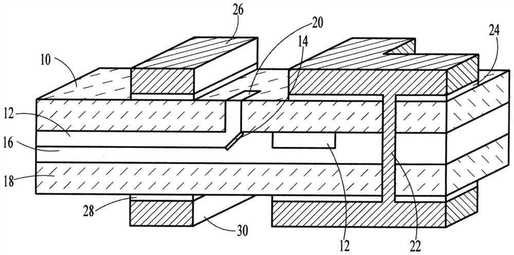
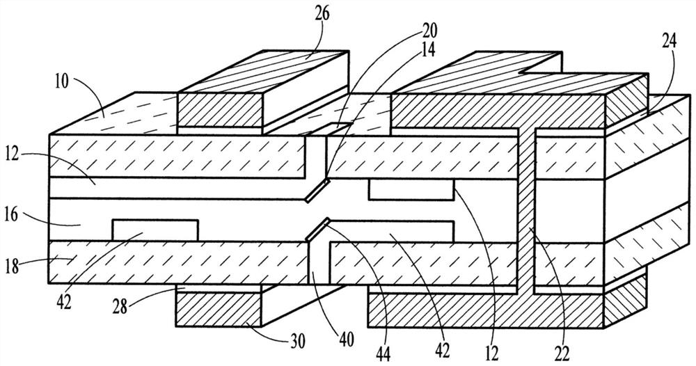
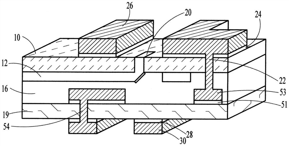
[0020] The invention discloses various versions of integrated electro-optical flexible circuit board (EOFCB). The functions of these circuit boards include electronic and optical circuits, flexible electronic components, and glass materials. Electronic circuits typically have low speed signals and are often used for power distribution with lower circuit density. Optical circuits typically have high-speed signals and high circuit density. Flexible electronics have a small profile and are relatively inconspicuous, they generally have a high wiring density and are foldable and bendable. Glass materials have smooth, transparent surfaces and low dielectric signal loss.

[0021] The concept of the present invention is to embed an optical circuit on a flexible electronic circuit, and the fabrication will take place on the same glass plate used for the flexible electronic circuit to provide better isolation characteristics. The present invention uses an optical adhesive to form a c...


PUM

PropertyMeasurementUnit
thicknessaaaaaaaaaa
thicknessaaaaaaaaaa
thicknessaaaaaaaaaa

Abstract

An integrated electro-optical circuit board comprising a first flexible substrate (10) having a top side and a bottom side, at least one first optical circuit (12) located on the bottom side of the first flexible substrate (10) and connected to the top side thereof through a filling hole (20), at least one first metal line (26) located on the top side of the first flexible substrate (10), connecting the bottom side of the first flexible substrate (10) to a second flexible substrate (18), an optical adhesive layer (16) on the top side, and at least one second metal line (30) located on the bottom side of the second flexible substrate (18) and connected to the at least one first metal line (26) through a filling hole (20) passing through the second flexible substrate (18), the optical adhesive layer (16) and the first flexible substrate (10).

Description

technical field [0001] This application relates to integrated circuit boards, and in particular to integrated optical circuits having electronic circuit boards. Background technique [0002] To support future devices such as high-performance computing (HPC) for high-speed, high-capacity data transfer, optical interconnects are the technology of choice. Traditional electronic circuits with copper interconnects are no longer adequate due to their data bandwidth limitations and signal integrity issues. Optical interconnects offer numerous advantages for high-performance devices, enabling massive data transfer rates with low attenuation / loss, delay, and power consumption, and low power consumption, while being virtually immune to electromagnetic interference and noise. Meanwhile, the electrical interconnect is more suitable for power distribution and signal processing and control. Electronic interconnection is also a mature technology with a well-established infrastructure in ...

Claims


Application Information

Patent Timeline
Patent Type & Authority Applications(China)
IPC IPC(8): G02B6/42H05K1/02
CPCH05K1/0274H05K2201/10121H05K2201/2054H05K2201/0108H05K1/028H05K2201/055H05K1/189H05K2201/0154G02B6/4214G02B6/4281H05K1/141H05K1/147H05K3/361H05K2201/045
Inventor 潘宝梁张志华罗塔森·杰森
Owner COMPASS TECH
Learn More