High-temperature-resistant oil pipe joint and preparation method thereof

A technology for oil pipe joints and high temperature resistance, which is applied in the direction of pipes/pipe joints/fittings, pipeline protection, threaded connections, etc. It can solve the problems of poor high temperature resistance of oil pipe joints, failure to find product defects, and inability to inspect product quality. Effects of service life, improvement of adhesion and thickness, and improvement of high temperature resistance

Pending Publication Date: 2022-07-12
广州市伟力达机电有限公司
View PDF11 Cites 0 Cited by
  • Summary
  • Abstract
  • Description
  • Claims
  • Application Information

AI Technical Summary

Problems solved by technology

[0006] Aiming at the deficiencies of the prior art, the object of the present invention is to provide a high-temperature-resistant oil pipe joint and its preparation method. It will accelerate the aging of the joint, the service life is short, and the quality of the product cannot be tested during the preparation process, and the internal defects of the product cannot be found, which reduces the technical problem of product quality.

Method used


Image

  • High-temperature-resistant oil pipe joint and preparation method thereof
  • High-temperature-resistant oil pipe joint and preparation method thereof
  • High-temperature-resistant oil pipe joint and preparation method thereof

Examples


Embodiment 1

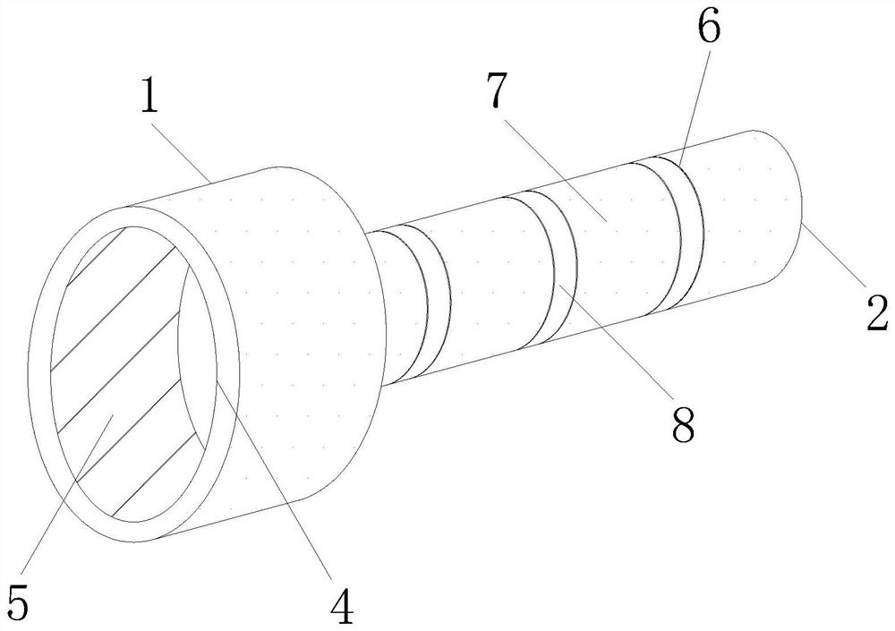
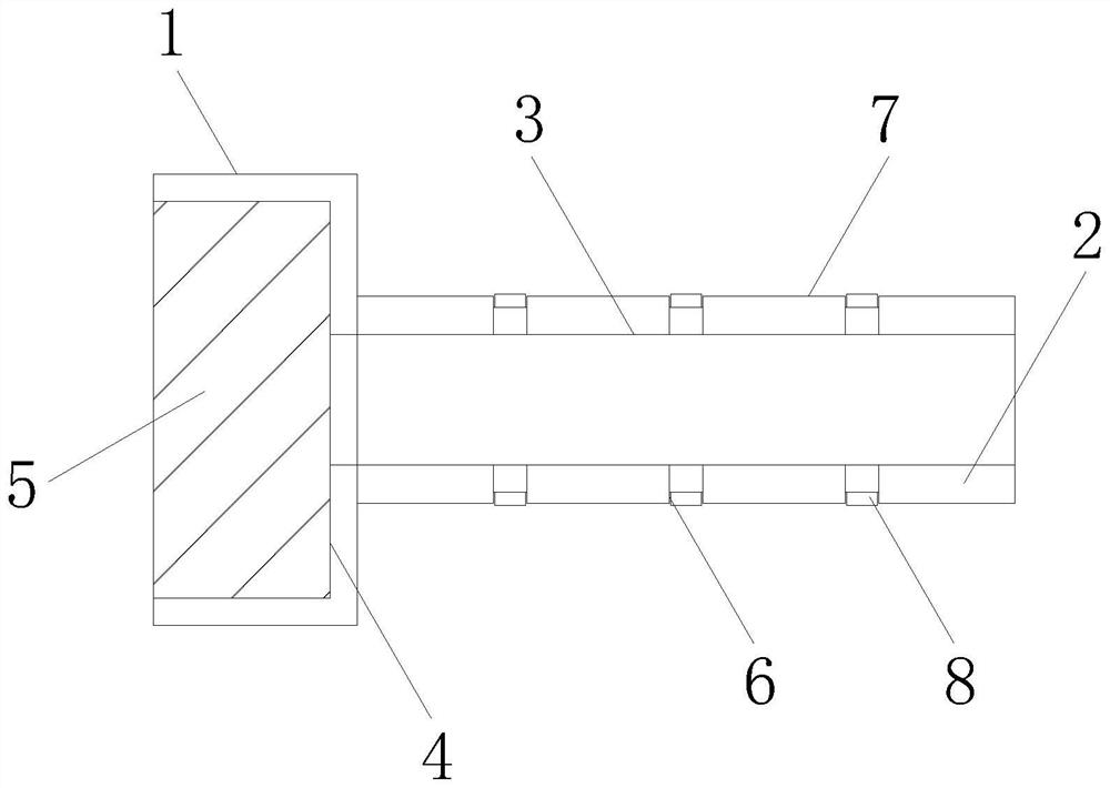
[0035] The specific embodiment is a high temperature resistant oil pipe joint, and its three-dimensional structure schematic diagram is as follows: figure 1 The schematic diagram of its cross-sectional structure is shown in figure 2 As shown, the oil pipe joint includes an inner threaded joint 1 and an insertion rod 2 fixed to the right end of the inner threaded joint 1; wherein, the insertion rod 2 is provided with an inner through hole 3, and the inner threaded joint 1 is provided with an inner through hole 3 that is the same as the inner through hole 3. The groove 4 and the thread 5 of the concentric structure are provided with annular grooves 6 distributed at equal distances on the outside of the insertion rod 2. The annular groove 6 is sleeved with a sealing ring 7, and the surfaces of the inner threaded joint 1 and the insertion rod 2 are provided with high temperature resistant coating. Layer 8.

[0036] The material of the female threaded joint 1 and the plunger 2 is...

Embodiment 2

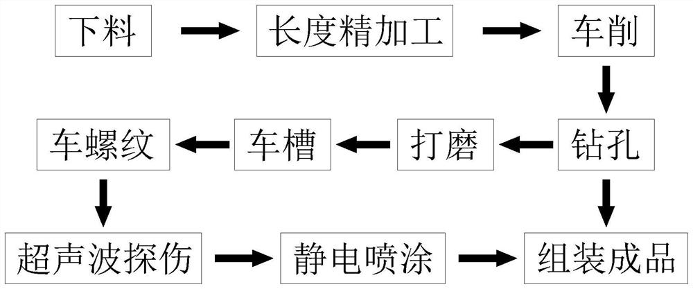
[0054] When using the preparation method of this technical solution to make oil pipe joints, the steps are as follows:

[0055] Step 1: Blanking: According to the diameter of the oil pipe joint, select the bar of the corresponding specification, the length of the blanking = the length of the oil pipe joint + the blanking allowance, and the blanking allowance is 5mm;

[0056] Step 2: Length finishing: Grind both ends of the bar so that the error between the length of the bar and the length of the tubing joint is less than ±0.3mm;

[0057] Step 3: Turning: Put the bar on the CNC lathe and clamp it, set the cutting speed and feed for rough machining, and turn the bar into a stepped cylindrical material. When the diameter of the stepped cylindrical material is different from the diameter of the oil pipe joint When it is less than 8mm, adjust the cutting speed and feed for finishing until the dimensional error between the stepped cylindrical material and the oil pipe joint is less ...


PUM

PropertyMeasurementUnit
thicknessaaaaaaaaaa

Abstract

The invention discloses a high-temperature-resistant oil pipe joint and a preparation method thereof, and aims to solve the problems that in the prior art, an oil pipe joint is poor in high-temperature resistance, aging of the joint is accelerated due to long-time high-temperature operation, the service life is short, the quality of a product cannot be detected in the preparation process, and the production cost is low. The defects in the product cannot be found, and the quality degree of the product is reduced. The oil pipe joint comprises an internal thread joint and an insertion rod fixed at the right end of the internal thread joint. According to the oil pipe joint and the preparation method thereof, by means of the design of the high-temperature-resistant coating, the high-temperature-resistant effect is achieved, the high-temperature-resistant performance of the oil pipe joint is improved, it is avoided that aging of the joint is accelerated due to long-time high-temperature operation, and the service life of the oil pipe joint is prolonged; therefore, product cracks or other defects hidden inside can be found in time, normal use of the oil pipe joint is guaranteed, and the effect of the high-temperature-resistant finish paint is guaranteed.

Description

technical field [0001] The invention belongs to the technical field of oil pipe joints, and particularly relates to a high temperature resistant oil pipe joint and a preparation method thereof. Background technique [0002] After drilling, the oil pipe transports crude oil and natural gas from the oil and gas layer to the surface. The oil pipe can withstand the pressure generated during the mining process. When the oil pipe is working, it needs to cooperate with the use of joints to connect the oil pipe and another oil pipe. [0003] At present, the invention patent with the patent number of CN201610902476.3 discloses a pipe joint processing technology, which includes the following steps: a. material preparation, selecting the corresponding bar material according to the diameter size and steel material; b. turning processing, turning and roughing the pipe joint The outer diameter is 1 and a margin of 0.03-0.05MM is left, and the outer diameter of the outer thread is turned a...

Claims


Application Information

Patent Timeline
Patent Type & Authority Applications(China)
IPC IPC(8): B23P15/00F16L15/00F16L57/04F16L58/18
CPCB23P15/00F16L15/00F16L57/04F16L58/182
Inventor 罗展欣
Owner 广州市伟力达机电有限公司
Why Eureka
Try Eureka