
Rotary cross beam workbench

A technology for rotating worktables and worktables, which is applied in the direction of manufacturing tools, metal processing equipment, metal processing machinery parts, etc. It can solve the problems of high speed, low precision, and many internal bearing structures of rotary worktables, and achieve the reduction of moving space requirements , high-efficiency and high-precision processing, and the effect of improving space utilization

Active Publication Date: 2022-07-12
SHENZHEN XIANGJU IND CO LTD
View PDF12 Cites 0 Cited by
  • Summary
  • Abstract
  • Description
  • Claims
  • Application Information

AI Technical Summary

Problems solved by technology

[0003] 1. The rotary table has only one workpiece installation platform. When the machine tool is running, the workpiece processing and installation cannot be carried out at the same time, and the efficiency is low;
[0004] 2. The workpiece mounting table of the rotary table has poor flexibility in adjusting the workpiece orientation and angle, and the single-station processing efficiency is low;
[0005] 3. The traditional rotary table adopts traditional power transmission methods such as reducers or worm gears, which are large in size and low in precision;
[0006] 4. Due to the high speed of the rotary table, there are many internal bearings and other structures, the volume is too large, and the installation and design are inconvenient

Method used


Image

  • Rotary cross beam workbench
  • Rotary cross beam workbench
  • Rotary cross beam workbench

Examples


Embodiment Construction

[0031] Combine below Figures 1~7 The embodiments of the present invention will be described in detail.

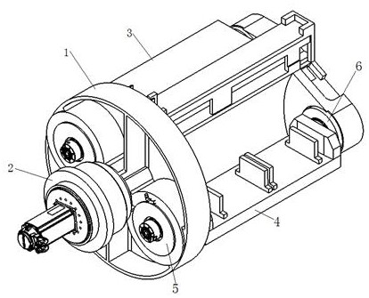
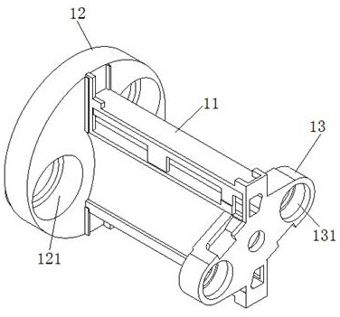
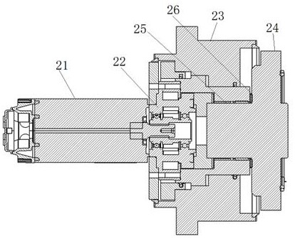
[0032]The rotary beam table includes a beam rotary table 1 and a rotary power assembly 2 that drives the beam rotary table 1 to rotate. 1. Parallel and multiple, multiple rotating worktables 3 are evenly distributed in the circumferential direction of the beam turntable 1, the workpiece is clamped on the rotating worktable 3, and the rotary power assembly 2 and the rotating worktable 3 are controlled by the control system.

[0033] In the above-mentioned rotary beam table, the rotary table 3 is mounted on the beam rotary table 1 and evenly distributed in the circumferential direction of the beam rotary table 1. The rotary power assembly 2 drives the beam rotary table 1 to rotate, so that the plurality of rotary table 3 are synchronized. Rotating to different stations, the workpieces on each rotating table 3 complete the corresponding processing procedures at their respect...


PUM


Abstract

The rotary cross beam workbench comprises a cross beam rotary table and a rotary power assembly for driving the cross beam rotary table to rotate, and is characterized in that a plurality of rotary workbenches capable of rotating are arranged on the cross beam rotary table, are parallel to the cross beam rotary table and are uniformly distributed in the circumferential direction of the cross beam rotary table; a workpiece is clamped on the rotary workbench, and the rotary power assembly and the rotary workbench are both controlled by the control system. Alternate rotation of the stations and automatic change of the directions of the workpieces are achieved, the rotary workbench has two rotational freedom degrees of revolution and rotation, the workbench high in space utilization rate and compact in structure is formed, multi-station and multi-direction machining can be achieved by clamping the workpieces at a time, the automation level of workpiece machining is improved, labor intensity is reduced, and production efficiency is improved. The space utilization rate of the rotary cross beam workbench is increased, multi-station and multi-direction high-efficiency and high-precision machining is achieved, and the precision and reliability of workpiece machining are improved.

Description

technical field [0001] The invention relates to a rotary beam worktable, which is used for multi-station and multi-angle processing of workpieces. Background technique [0002] In the process of manufacturing workpieces, most of the work needs to be drilled, ground, and assembled wedges on different inclined planes. In order to facilitate operation and ensure quality, assembly equipment is often used to clamp the workpiece, and then the selected processing position is finely processed. The existing assembly equipment is cumbersome to flip the workpiece, and even requires manual assistance, resulting in inconvenient assembly, high labor intensity for workers, certain safety hazards, and low inversion accuracy, which in turn leads to low assembly quality. With the development of the machinery industry, the use of CNC turntables for accurate and rapid indexing has become an indispensable part of the process. The main defects of the current CNC rotary table are: [0003] 1. T...

Claims


Application Information

Patent Timeline
Patent Type & Authority Applications(China)
IPC IPC(8): B23Q1/25B23Q11/12
CPCB23Q1/25B23Q11/121Y02P70/10
Inventor 罗义乔志东陈亚琴
Owner SHENZHEN XIANGJU IND CO LTD
Learn More