
Permanent magnet coupler copper disc and mounting disc potting heat conduction structure

A technology for mounting disks and couplings, which is applied in permanent magnet clutches/brakes, electromechanical devices, transportation and packaging, etc., and can solve problems such as inability to effectively ensure effective heat conduction between copper disks and mounting disks, and dust entry.

Pending Publication Date: 2022-07-12
CCTEG SHENYANG RES INST +1
View PDF0 Cites 0 Cited by
  • Summary
  • Abstract
  • Description
  • Claims
  • Application Information

AI Technical Summary

Problems solved by technology

[0003] In the field of traditional magnetic coupling design, when the machining accuracy is relatively high between the copper plate and the mounting plate, there is a gap between the copper plate and the mounting plate, and the air in the gap is a poor conductor of heat. , and it is easy to cause dust in the air to enter the gap, so it cannot effectively ensure the effective heat conduction between the copper plate and the mounting plate

Method used


Image

  • Permanent magnet coupler copper disc and mounting disc potting heat conduction structure
  • Permanent magnet coupler copper disc and mounting disc potting heat conduction structure

Examples


Embodiment 1

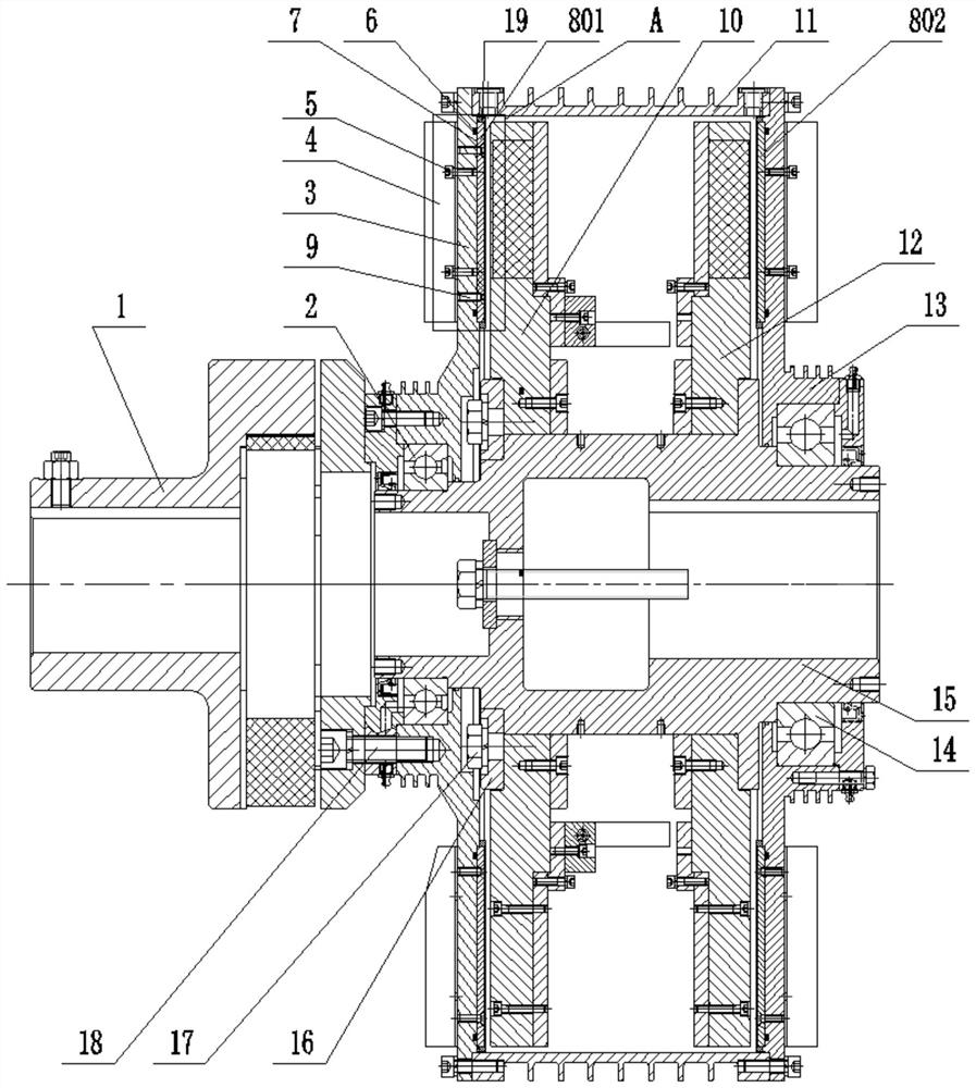
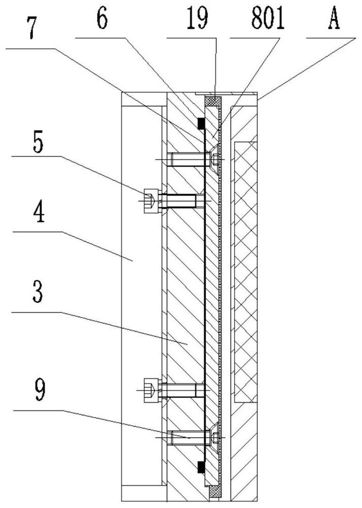
[0021] like figure 1 and figure 2 As shown, a heat conduction optimization technology of permanent magnet coupling copper plate and mounting plate potting includes input mounting plate 3, input copper plate 801, output mounting plate 13 and output copper plate 802; the input mounting plate 3 and the output mounting plate The disks 13 are respectively mounted on both sides of the output square shaft assembly 15 through the input deep groove ball bearing 2 and the output deep groove ball bearing 14, and the input mounting disk 3 and the output mounting disk 13 are respectively mounted on the input deep groove ball bearing 2 and the output deep groove ball bearing 2. On the outer ring of the groove ball bearing 14, the input deep groove ball bearing 2 and the inner ring of the output deep groove ball bearing 14 are respectively installed on both sides of the output square shaft assembly 15, and the inner sides of the input installation plate 3 and the output installation plate 1...


PUM


Abstract

A permanent magnet coupler copper disc and mounting disc potting heat conduction structure comprises an input mounting disc. The input installation disc and the output installation disc are installed on the two sides of the output square shaft assembly respectively, the inner side of the input installation disc and the inner side of the output installation disc are in threaded connection with an input copper disc and an output copper disc through copper disc fastening screws respectively, and heat conduction silicone grease is smeared between the input copper disc and the input installation disc and between the output copper disc and the output installation disc. A magnetic disc assembly is installed on a square shaft of the output square shaft assembly, the input installation disc is in threaded connection with an input assembly through input assembly installation bolts, the top of the input installation disc and the top of the output installation disc are sleeved with cylinders, and cooling fins are installed on the outer side of the input installation disc and the outer side of the output installation disc through cooling fin fastening screws respectively. And heat conduction silicone grease is coated between the copper disc and the mounting disc to fill the gaps, so that heat conduction is smoother. Resin is smeared on the outer surface of the copper disc for a vacuum encapsulation technology, so that vacuum insulation and effective sealing between the copper disc and the mounting disc are ensured.

Description

technical field [0001] The invention belongs to the technical field of couplers, in particular to a potting heat conduction structure of a copper plate and a mounting plate of a permanent magnet coupler. Background technique [0002] In the field of magnetic coupling design, there is a magnetic coupling, which drives the conductor rotor to cut magnetic lines of force in the strong magnetic field generated by the permanent magnet rotor when the motor rotates, thus generating eddy currents in the conductor disk. Thereby, the anti-magnetic field and the magnetic field of the permanent magnet rotor cut the magnetic field line to drive the rotation, and the number of revolutions is controlled by controlling the air gap between the conductor rotor and the permanent magnet rotor. [0003] In the field of traditional magnetic coupling design, when the machining accuracy is relatively high between the copper plate and the mounting plate, there is a gap between the copper plate and th...

Claims


Application Information

Patent Timeline
IPC IPC(8): H02K9/22H02K5/124H02K5/10H02K49/10H02K16/02
CPCH02K9/227H02K9/223H02K5/124H02K5/10H02K49/108H02K16/025Y02T10/64
Inventor 王雷朱玉芹刘昊田冠华谢深王海波周海江张旭姜宇张维娜
Owner CCTEG SHENYANG RES INST
Learn More