

Odor treatment device based on sludge heat drying and garbage power generation
A technology of waste power generation and treatment device, which is applied in the fields of sludge treatment, water/sludge/sewage treatment, electromechanical devices, etc., which can solve the discomfort of the staff, the adverse effect of the heat dissipation effect of the driving motor, and the easy adhesion under the filter plate. Superficial problems, to achieve the effect of speeding up the mixing speed
- Summary
- Abstract
- Description
- Claims
- Application Information
AI Technical Summary
Problems solved by technology
Method used
Image

Examples
Embodiment 1
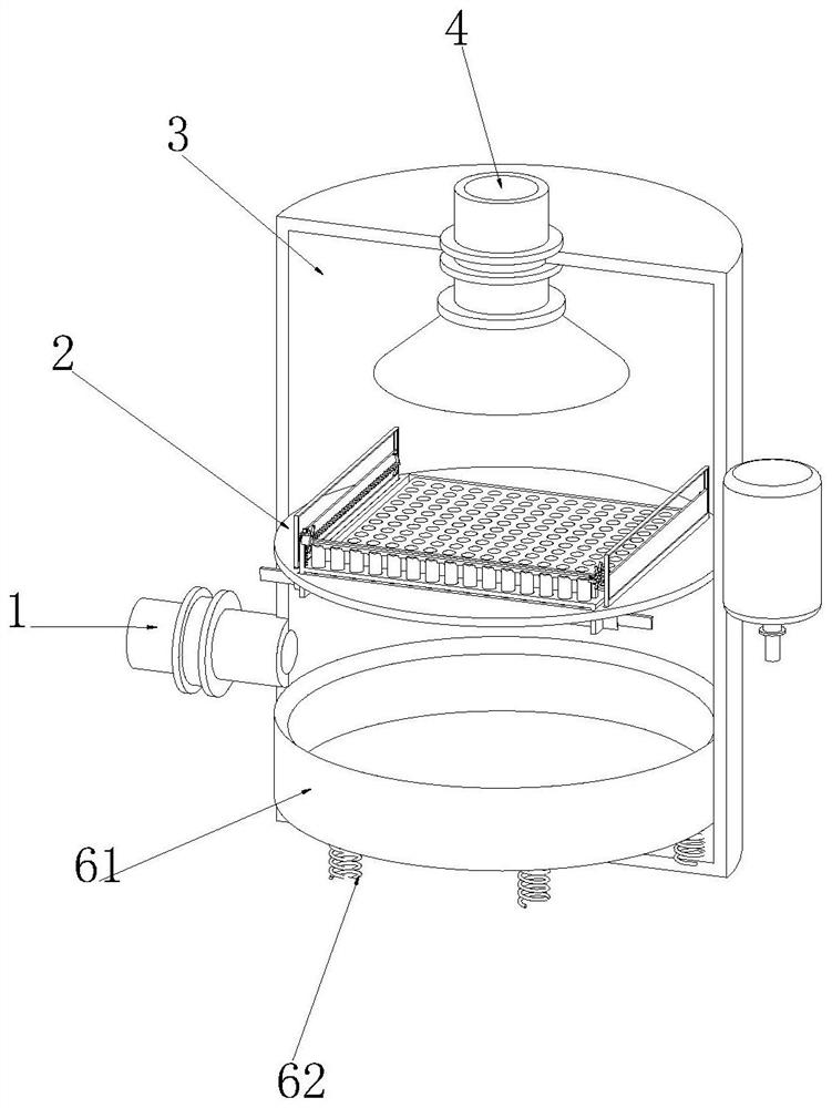
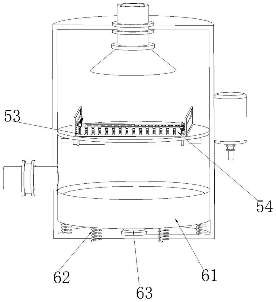
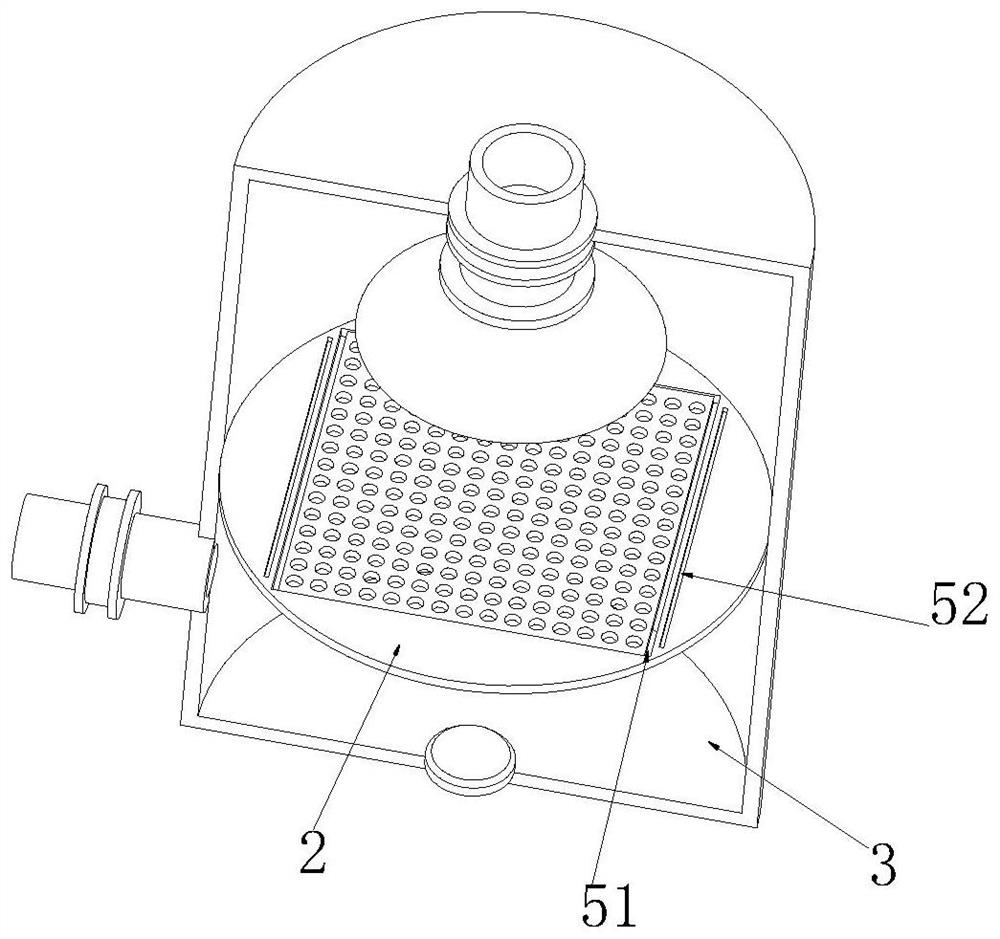
[0034] see Figure 1-8As shown, an odor treatment device based on sludge thermal drying and waste-to-energy generation includes an air inlet pipe 1, a filter plate 2, a treatment box 3 and an air extraction pipe 4, and an air inlet pipe 1 is connected to one side of the outer side wall of the treatment box 3. , the middle position of the inner side wall of the treatment box 3 is connected with a filter plate 2, the upper surface of the treatment box 3 is connected with an exhaust pipe 4, the upper surface of the filter plate 2 is provided with frame moving grooves 51 on both sides, and the upper surface of the filter plate 2 is two. A mounting slot 52 is opened at the position close to the frame moving slot 51 on the side, and the inner side wall of the frame moving slot 51 is slidably connected with a trash filter frame 53. Sliding, the upper surface of the filter frame 53 is connected with a number of evenly distributed cleaning rods 54, and a number of evenly distributed cl...
Embodiment 2
[0038] see Figure 9-11 As shown, sliding grooves 64 are provided on both sides of the lower surface of the fixed scraper 55, and a reciprocating plate 65 is slidably connected to both sides of the inner side wall of the sliding groove 64. The lower end of the deodorant box is connected with the spray head 610 through a pipeline, a liquid level gauge is arranged inside the processing box 3, a reciprocating screw 66 is rotatably connected to the inner side wall of the sliding groove 64, and the reciprocating plate 65 operates on the outside of the rotating reciprocating screw 66. Left and right reciprocating motion, the middle position of the reciprocating screw 66 is connected with a transmission gear 612, the transmission gear 612 and the drive gear 69 are mutually fitted and driven to rotate, and the fixed scraper 55 inside the corresponding transmission gear 612 The position of the transmission gear 612 is rotatably connected with the transmission shaft 611. Driving gear 69...
Embodiment 3
[0042] see Figure 12 As shown, a water tank 72 is connected to the upper surface of the filter frame 53 near the drive motor 516, and a movable plug 71 is slidably connected to the inner wall of the water tank 72. The upper end of the movable plug 71 is connected with the connecting plate 521, and is driven by the connecting plate 521. The upper surface of the movable plug 71 and the inner lower surface of the water tank 72 are connected with a one-way valve 74. When the movable plug 71 moves upward in the water tank 72, the one-way valve on the movable plug 71 74 is closed, the one-way valve 74 at the bottom of the water tank 72 is opened, and the water flow can flow into the water tank 72 from the position of the connecting pipe 73. When the movable plug 71 moves downward in the water tank 72, the one-way valve 74 on the movable plug 71 is opened. , the one-way valve 74 at the bottom of the water tank 72 is closed, and the water inside the water tank 72 below the movable pl...
PUM
 Abstract
Description
Claims
Application Information