Cutter bar of modular cutter and modular cutter

A modular and cutting tool technology, which is applied to the accessories of tool holders, tools for lathes, manufacturing tools, etc., can solve the problems of difficult control of tool dynamic balance, tool breakage, affecting tool processing life and processing quality, etc., to improve Processing life and processing quality, satisfaction of rigidity and strength, and effect of improving material utilization

Pending Publication Date: 2022-07-22
XIAMEN GOLDEN EGRET SPECIAL ALLOY
View PDF0 Cites 0 Cited by
  • Summary
  • Abstract
  • Description
  • Claims
  • Application Information

AI Technical Summary

Problems solved by technology

[0004] 1. For low-power machine tools, the use of modular tools with a large overall weight cannot meet the processing power requirements, making it unusable;
[0005] 2. When using heavy modular cutting tools for processing, it is difficult to control the dynamic balance of the cutting tools, which affects the processing life and processing quality of the cutting tools. In severe cases, the cutting tools may even break and threaten the safety of personnel;
[0006] 3. The rod body adopts a solid structure, which does not make full use of the tool material, resulting in a waste of some resources

Method used


Image

  • Cutter bar of modular cutter and modular cutter
  • Cutter bar of modular cutter and modular cutter
  • Cutter bar of modular cutter and modular cutter

Examples


Embodiment 2

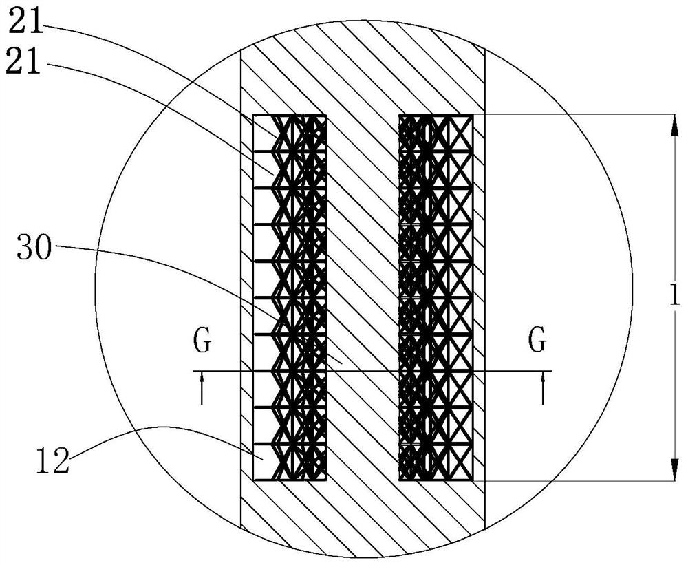
[0058] A tool holder and a modular tool for a modular tool, the main structure of which is the same as that of the first embodiment, the difference is: see Figure 11 , the diameter of the maximum circumscribed circle of the load-bearing structure 30 gradually increases from the end of the locking portion 11 to the other end of the rod body 10 , that is, the end of the tool handle.

[0059] Since different parts of the cutter bar bear different bending moments during machining, the farther away from the locking portion 11 of the bar body 10, the greater the bending moment, and the higher the strength and rigidity requirements are. In this embodiment, by reasonably setting the maximum circumscribed circle diameter of the section of the load-bearing structure 30 at different positions of the rod body 10 , the weight of the tool is further reduced while satisfying the structural strength and rigidity requirements at different positions.

[0060] In this embodiment, since the maxi...


PUM


Abstract

The cutter bar comprises a bar body, one end of the bar body is provided with a locking part, the other end of the bar body serves as a handle part, and the cutter bar is characterized by further comprising a net rack structure and a force bearing structure; a cavity is formed between the locking part and the handle part of the rod body; the force bearing structure is fixedly arranged in the cavity in a penetrating mode in the axial direction of the rod body, and the two ends of the force bearing structure are connected with the two corresponding end walls of the cavity; the grid structure is located between the side wall of the cavity and the periphery of the force bearing structure. On the premise of meeting the rigidity and strength requirements required by tool machining, the weight of the modular tool is greatly reduced, tool dynamic balance control in the tool machining process is facilitated, the tool machining life is prolonged, the tool machining quality is improved, meanwhile, tool material loss is reduced, the material utilization rate is increased, and the tool cost is reduced.

Description

technical field [0001] The invention relates to the field of cutting tools, in particular to a modular tool holder and a modular tool. Background technique [0002] With the development of processing and manufacturing technology, modular tools are one of the development directions of CNC tools in the future. Modular tools have the characteristics of reducing tool change and installation time, improving tool utilization, and improving tool standardization. It is widely used in processing industries such as molds. [0003] The modular tool includes the tool head part with cutting function and the tool holder part connected with the machine tool holder. The tool head part and the tool holder part are connected by means of threads, etc. The tool holder part of the traditional modular tool is a rod-shaped solid structure , Some modular tools with large diameter and long overhang are heavy, and have the following problems: [0004] 1. For low-power machine tools, the use of modu...

Claims


Application Information

Patent Timeline
Patent Type & Authority Applications(China)
IPC IPC(8): B23B27/16
CPCB23B27/16
Inventor 王珏洪培强李清华林亮亮代平
Owner XIAMEN GOLDEN EGRET SPECIAL ALLOY
Why Eureka
Try Eureka