
Laser marking machine based on triangulation ranging method

A laser marking machine and triangulation ranging technology, which is applied in the background field of marking machines, can solve the problems of uneven length and width of objects, shaking, irregular shapes, etc., so as to avoid marking mistakes, achieve good clamping effect and reduce effect of loss

Pending Publication Date: 2022-07-22
创轩常熟激光科技有限公司
View PDF17 Cites 0 Cited by
  • Summary
  • Abstract
  • Description
  • Claims
  • Application Information

AI Technical Summary

Problems solved by technology

[0003] However, when the marking machine is used, due to the problems of different lengths and widths and irregular shapes of the objects, it often appears that the placement is unstable, and the problem of shaking during the marking process will affect the marking effect. Therefore, it is necessary Provide a laser marking machine based on the triangular ranging method, which can achieve the effect of clamping marking

Method used


Image

  • Laser marking machine based on triangulation ranging method
  • Laser marking machine based on triangulation ranging method
  • Laser marking machine based on triangulation ranging method

Examples


Embodiment Construction

[0034] The following disclosure provides many different embodiments or examples for implementing different structures of the present application. To simplify the disclosure of the present application, the components and arrangements of specific examples are described below. Of course, they are only examples and are not intended to limit the application. Furthermore, this application may repeat reference numerals and / or reference letters in different instances for the purpose of simplicity and clarity, and does not in itself indicate a relationship between the various embodiments and / or arrangements discussed. In addition, this application provides examples of various specific processes and materials, but one of ordinary skill in the art will recognize the application of other processes and / or the use of other materials.

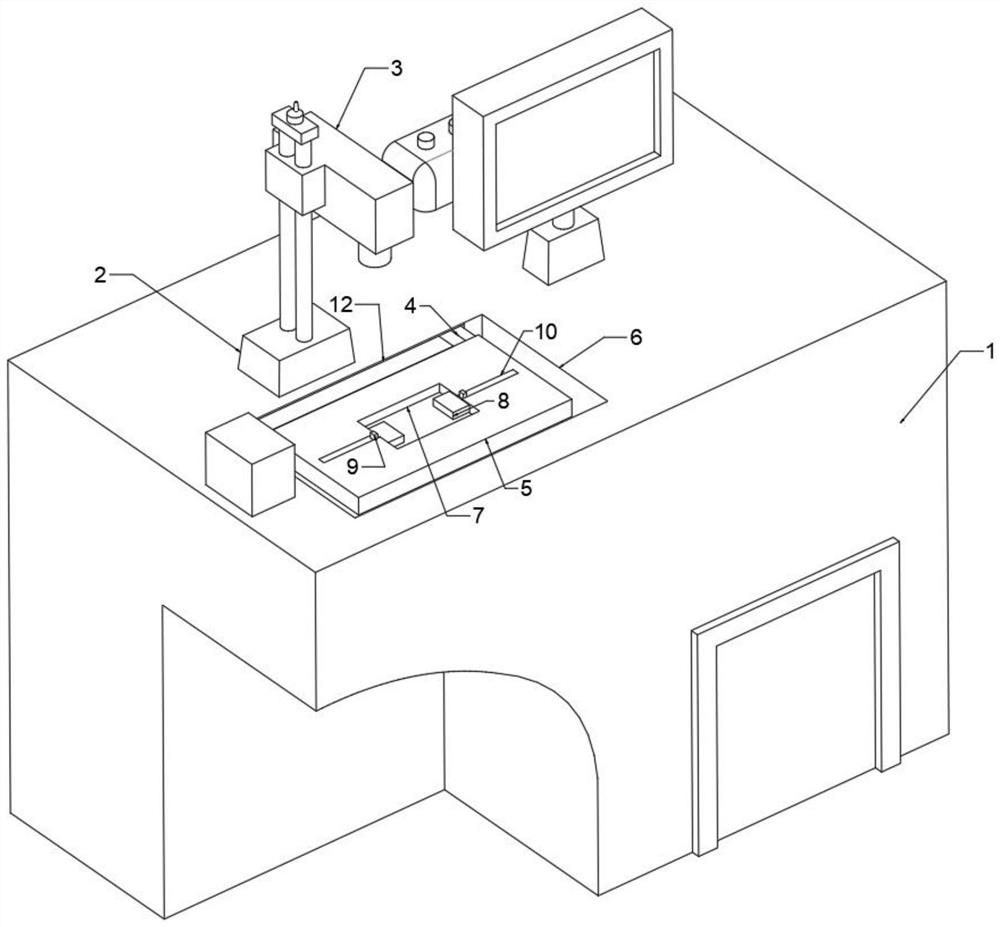
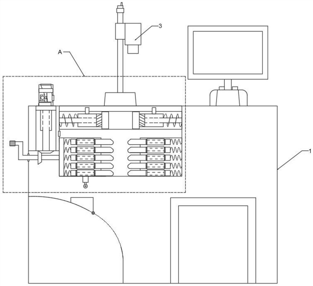
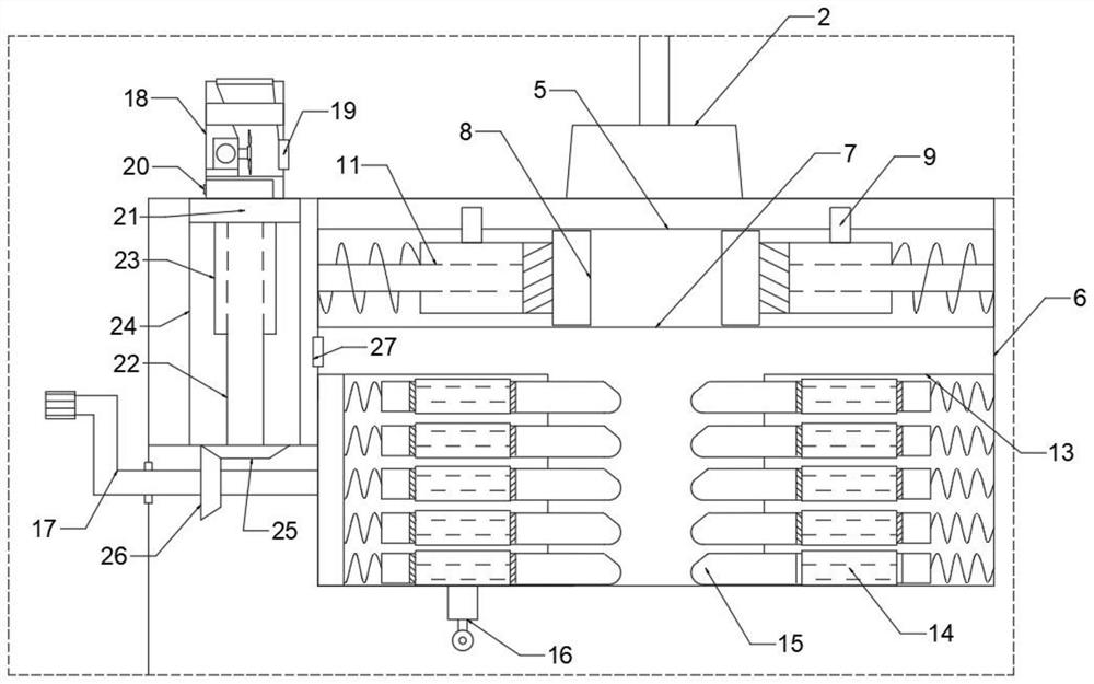
[0035] see Figure 1-3 , the present invention provides a technical solution: a laser marking machine based on the triangulation ranging method, comprising...


PUM


Abstract

The invention discloses a laser marking machine based on a triangulation ranging method, and the machine comprises a marking assembly which carries out the quick marking and marking of the surface of an object through laser; the clamping assembly is used for clamping objects in corresponding forms according to different shapes of the objects, so that the to-be-marked surfaces of the objects can correspond to the marking assembly more stably; the dust removal assembly is used for absorbing dust smoke generated in the marking process; the marking assembly comprises a main cabinet, a base, a marking head, a connecting rod, a control panel and a storage groove. The base is fixedly installed at the top of the main cabinet, the connecting rod is welded to the top of the base, the marking head is slidably connected to the top of the connecting rod, the control panel is fixedly connected to the upper surface of the main cabinet, and the storage groove is formed in the top of the main cabinet and right faces the lower portion of the marking head. The clamping assembly comprises a conventional clamping assembly and a special-shaped clamping assembly; according to the invention, the clamping and marking functions are conveniently and efficiently realized.

Description

technical field [0001] The invention is applied to the background of the marking machine, and the name is a laser marking machine based on the triangular ranging method. Background technique [0002] Laser marking machines use laser beams to permanently mark the surface of various substances. The effect of marking is to expose the deep material through the evaporation of the surface material, so as to engrave exquisite patterns, trademarks and characters. Laser marking machines are mainly divided into carbon dioxide laser marking machines, semiconductor laser marking machines, and fiber laser marking machines. And YAG laser marking machine, laser marking machine is mainly used in some occasions requiring finer and higher precision. Used in electronic components, integrated circuits, electrical appliances, mobile communications, hardware products, tool accessories, precision instruments, glasses and clocks, jewelry, auto parts, plastic buttons, building materials, PVC pipes,...

Claims


Application Information

Patent Timeline
Patent Type & Authority Applications(China)
IPC IPC(8): B23K26/362B23K26/70B23K37/04
CPCB23K26/362B23K26/702B23K37/0435
Inventor 余德山
Owner 创轩常熟激光科技有限公司
Learn More