Compressor double-cylinder crankshaft machining equipment

A crankshaft processing and compressor technology, applied in the field of crankshaft processing, can solve the problems of blockage of lubricating fluid flow, variation in the dimension deviation of the included angle of the crankshaft, and inability to polish and grind, so as to meet the dimensional accuracy of the included angle of the crankshaft and ensure the overall strength. Effect

Active Publication Date: 2022-07-22
芜湖德善数控科技有限公司
View PDF12 Cites 0 Cited by
  • Summary
  • Abstract
  • Description
  • Claims
  • Application Information

AI Technical Summary

Problems solved by technology

[0002] The rotation of the crankshaft is the power source of the reciprocating compressor. For the consideration of wear resistance and overall strength, one-piece molding is often used. When re-planning the displacement of the reciprocating compressor, the crank angle of the double-cylinder crankshaft will change. change, it is necessary to replace the casting or forging mold, and the dimensional deviation of the included angle of the crankshaft will change greatly after reprocessing the workpiece made by multiple sets of molds. However, for the oil groove on the outer edge of the crankshaft shaft, it cannot be polished and ground, which leads to the obstruction of the flow of lubricating fluid in the oil groove when the compressor is working, and the crankshaft heats up significantly when it is working for a long time

Method used


Image

  • Compressor double-cylinder crankshaft machining equipment
  • Compressor double-cylinder crankshaft machining equipment
  • Compressor double-cylinder crankshaft machining equipment

Examples


Embodiment Construction

[0021] In order to make the technical means, creative features, achievement goals and effects realized by the present invention easy to understand, the present invention will be further described below with reference to the specific embodiments.

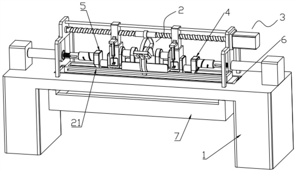
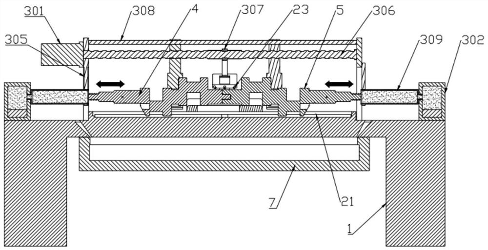
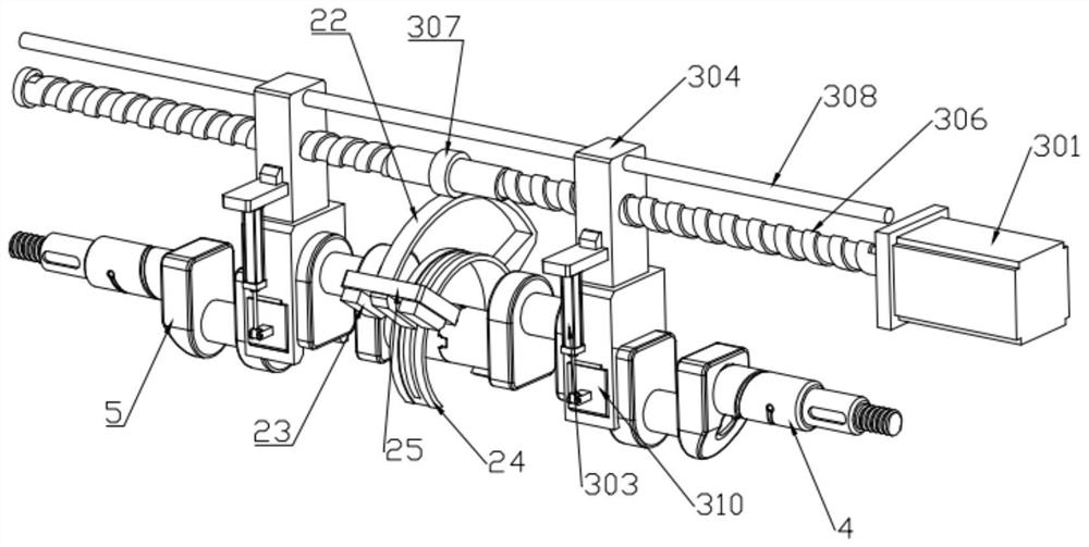
[0022] like Figure 1 to Figure 6 As shown, a compressor double-cylinder crankshaft processing equipment includes a frame 1, a chip removal and placement part 2 and a shaft groove fine grinding mechanism 3. The chip removal and placement part 2 is installed on the frame 1, and is divided into two parts The ends of the crankshaft 4 and the split mother crankshaft 5 are cleaned of wear debris. The frame 1 is provided with a flow port 6 at the lower end of the chip removal placing portion 2, and a recovery groove 7 is installed on the frame 1 below the flow port 6. The shaft groove fine grinding mechanism 3 is installed on the frame 1 and is used for high-precision grinding of the outer edges of the shafts and the oil grooves on the spl...


PUM


Abstract

The invention discloses compressor double-cylinder crankshaft machining equipment, and relates to the technical field of crankshaft machining, and the compressor double-cylinder crankshaft machining equipment comprises a rack, a scrap removal placing part and a shaft groove accurate grinding mechanism. According to the invention, the scrap removal placing part and the shaft groove fine grinding mechanism are arranged on the rack, the output end of the driving motor drives the two sliding positioning pieces to slide back and forth aiming at the split son crankshaft and the split mother crankshaft which are split, and the two sliding positioning pieces are driven by the output end of the driving motor to slide back and forth in the sliding process that the split son crankshaft and the split mother crankshaft are close to each other; a positioning column and a cross-shaped positioning groove at the end part of the split secondary crankshaft and a positioning hole and a cross-shaped positioning bulge at the end part of the split primary crankshaft complete automatic accurate grinding and polishing in a mutual ejection grinding manner, and a single set of mold can ensure the overall strength and meet the size precision of a crank throw included angle; and in the sliding process that the split secondary crankshaft and the split primary crankshaft are far away from each other, the spiral oil groove is gradually and precisely polished in an extruding, punching and grinding mode, the flowing smoothness of the lubricating liquid in the oil groove is guaranteed, and the heating degree is further reduced.

Description

technical field [0001] The invention relates to the technical field of crankshaft processing, in particular to a compressor double-cylinder crankshaft processing equipment. Background technique [0002] The rotation of the crankshaft is the power source of the reciprocating compressor. Due to the consideration of wear resistance and overall strength, one-piece molding is often used. When the displacement of the reciprocating compressor is re-planned, the crank angle of the two-cylinder crankshaft will occur. If it changes, the casting or forging dies must be replaced. The dimensional deviation of the included angle of the crankshaft will change greatly after the workpiece made of multiple sets of dies is reprocessed. However, the oil groove on the outer edge of the crankshaft cannot be polished and ground, so that the flow of the lubricating fluid in the oil groove is blocked when the compressor is working, and the crankshaft heats up significantly under long-term working co...

Claims


Application Information

Patent Timeline
Patent Type & Authority Applications(China)
IPC IPC(8): B24B5/42B24B5/35B24B41/06B24B41/00B24B57/02B24B55/03B08B3/02
CPCB24B5/42B24B5/35B24B41/06B24B41/00B24B57/02B24B55/03B08B3/02Y02P70/10
Inventor 雒应学
Owner 芜湖德善数控科技有限公司
Why Eureka
Try Eureka