Supercharge Your Innovation With Domain-Expert AI Agents!

Semi-permanent dam foundation structure of rubber dam for river regulation

A semi-permanent, rubber dam technology, applied in infrastructure engineering, sea area engineering, construction, etc., can solve problems such as reduction, achieve the effects of reducing dredging frequency, beautifying the environment, and improving efficiency

Pending Publication Date: 2022-07-22
洛阳水利建设投资集团有限公司
View PDF0 Cites 0 Cited by
  • Summary
  • Abstract
  • Description
  • Claims
  • Application Information

AI Technical Summary

Problems solved by technology

[0004] The purpose of the present invention is to solve the problem that a rubber dam with a span of tens of meters needs to be removed by a dredging ship to remove sediment. It provides a semi-permanent dam foundation structure of a rubber dam for river channel regulation. The anti-silting area with lever components is designed, and the downstream design of the settlement drainage area can make most of the sediment pass through the rubber dam and deposit on both sides of the river, which is convenient for manual direct cleaning, greatly improving the convenience and cost of dredging , which greatly reduces the frequency of dredging by dredging boats in front of the rubber dam. After simulation experiments, the time required to deposit the same height of sediment in front of the rubber dam is 2-3 times that of the original time.

Method used


Image

  • Semi-permanent dam foundation structure of rubber dam for river regulation
  • Semi-permanent dam foundation structure of rubber dam for river regulation
  • Semi-permanent dam foundation structure of rubber dam for river regulation

Examples


Embodiment 1

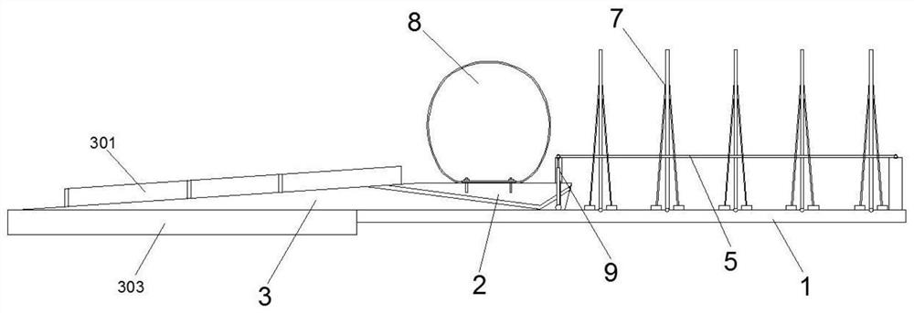
[0037] like figure 1 and 2 As shown, a semi-permanent dam foundation structure of a rubber dam for river management includes a raised base 2 that carries a rubber dam 8 in the river, that is, the rubber dam 8 is fixedly installed on the raised base 2, and the raised base 2 cuts off the river, so The upstream of the raised base 2 is provided with an anti-silting area 1, and the downstream is provided with a settlement drainage area 3. The raised base 2, the anti-silting area 1 and the settlement and drainage area 3 are all built with cement concrete on the river bed. The height of the anti-silting area 1 is The lowest, generally 2-5cm thick cement concrete layer is sufficient. The raised base 2 protrudes from the anti-siltation zone 1, and its height depends on the water flow of the river. The upstream of the drainage area 3 is connected with the lifting base 2, and the downstream is gradually lowered. There are several lever assemblies 7 distributed on the anti-siltation area...

Embodiment 2

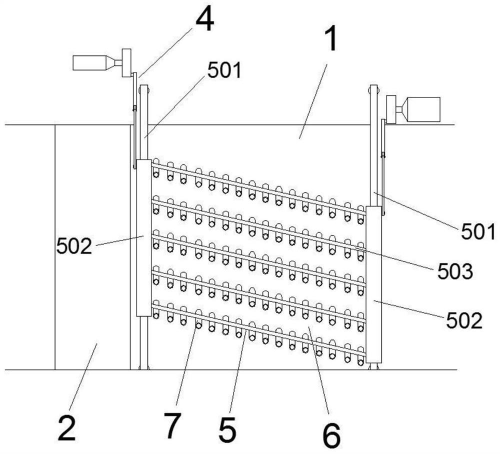
[0043] This embodiment is an improvement scheme made on the basis of Embodiment 1, and its main structure is the same as that of Embodiment 1. The improvement points are as follows: image 3 , 4 As shown in and 5, the reciprocating toggle mechanism 5 includes two horizontal support rods 501 spanning the width direction of the river. The horizontal support rods 501 are generally stainless steel pipes, and are located below the water surface after the rubber dam 8 is installed and stored, and in the middle. and both ends are supported by stainless steel pipes 504, the length of which is determined by the width of the river. One of the two horizontal support rods 501 is located on the water-facing side of the rubber dam 8, and the other is located further upstream. Two horizontal support rods An anti-siltation zone 1 is formed between 501, and each horizontal support rod 501 is provided with two sleeves 502 slid symmetrically along the center of the river. , so as to ensure that...

Embodiment 3

[0045] This embodiment is an optimization scheme made on the basis of Embodiment 2, and its main structure is the same as that of Embodiment 2. The optimization point is that the two casings 502 located on the same side of the river move in the same direction and move in the same direction. Movement means that when the two sleeves 502 are driven to and fro by the two crank-slider mechanisms 4 respectively, the movement directions are always consistent, that is, they move to the side close to the river bank or to the side close to the center of the river at the same time. move, and its moving speed and stroke are consistent, and the upstream one of the two sleeves 502 is closer to the center of the river than the initial position downstream; two sleeves located on the same horizontal support rod 501 The pipe 502 moves in an opposite direction. The anisotropic movement means that the two sleeves 502 on the same horizontal support rod 501 are respectively driven by the two crank-s...


PUM

PropertyMeasurementUnit
Heightaaaaaaaaaa
Thicknessaaaaaaaaaa
Thicknessaaaaaaaaaa

Abstract

A semi-permanent dam foundation structure of a rubber dam for river regulation comprises an anti-siltation area, a lifting base body and a sedimentation drainage area, deflector rod assemblies are distributed on the anti-siltation area, the deflector rod assemblies are connected in series through a connecting belt of a reciprocating deflector mechanism to form a multi-row structure, and the deflector rod assemblies are driven by a slider-crank mechanism to reciprocate in the direction perpendicular to water flow. Therefore, the deposited silt is stirred up and flows into the sedimentation drainage area after crossing the rubber dam; a plurality of partition walls are arranged on the sedimentation drainage area, a sedimentation flow channel for guiding the flowing direction of bottom-layer water flow is formed between every two adjacent partition walls, and the downstream of each sedimentation flow channel extends into sedimentation tanks arranged on the two sides of the river channel. By designing the anti-siltation area and the sedimentation drainage area with the shifting rod assemblies, most silt can be deposited on the two sides of a river channel after crossing the rubber dam, manual direct cleaning is facilitated, the convenience degree and cost of desilting are greatly improved, and the desilting frequency of a desilting ship in front of the rubber dam is reduced.

Description

technical field [0001] The invention relates to a rubber dam in the field of water conservancy facilities, in particular to a semi-permanent dam foundation structure of a rubber dam for river regulation. Background technique [0002] Rubber dam is a new type of water-retaining structure. It uses rubber and fiber synthetic tape as a dam bag, which is anchored on the dam foundation to form a closed flexible water-retaining structure. field. [0003] In the prior art, the dam foundation of the rubber dam only provides the installation base of the rubber dam, which is generally built with cement concrete in the river channel. In front of the rubber dam, manual dredging is required, and in the case of a wide river, such as a rubber dam with a span of several tens of meters, a dredging vessel is generally required to regularly dred the central area of ​​the river, which is not only troublesome, but also expensive. higher. SUMMARY OF THE INVENTION [0004] The purpose of the p...

Claims


Application Information

Patent Timeline
IPC IPC(8): E02B7/00E02B8/00E02B8/02E02D27/40E02D27/52
CPCE02B7/005E02B8/00E02B8/02E02D27/40E02D27/52E02B2201/02
Inventor 杨宁苛刘效妤赵毅铭王海岩闫坤梁晓菲介单单
Owner 洛阳水利建设投资集团有限公司
Features
  • R&D
  • Intellectual Property
  • Life Sciences
  • Materials
  • Tech Scout
  • Unparalleled Data Quality
  • Higher Quality Content
  • 60% Fewer Hallucinations
Learn More