Power output mechanism on battery car

A technology of power output and power output gear, which is applied in the direction of transmission, mechanical equipment, belt/chain/gear, etc. It can solve the problems of motor failure, wheel wear, and easy damage, so as to avoid loss and waste and save electricity , to avoid the effect of wear

Pending Publication Date: 2022-07-22
浙江无懈电机有限公司
View PDF0 Cites 0 Cited by
  • Summary
  • Abstract
  • Description
  • Claims
  • Application Information

AI Technical Summary

Problems solved by technology

[0002] At present, the power output mechanism of the battery car generally uses a brushless motor for power output. There is a Hall element inside the brushless motor. After the Hall element detects a signal, the brushless motor can be powered or cut off Electricity; the advantage of the Hall element is that the vehicle has better stability during operation, but the disadvantage is that it is easily damaged by external forces during use; the brushless motors without Hall are generally used in existing battery cars , although it avoids the problem that the Hall element is easily damaged, but when the vehicle is started, the motor needs to rotate 120° to measure the phase, so that the controller can know which line to supply power to. For things with heavy loads, because the wheels cannot rotate, the electrical signal may not be detected (the wheels cannot rotate, causing the motor to fail to meet the 120° rotation requirement). At the same time, if the user twists the switch hard, a pull Tire phenomenon (speed and torque mismatch), resulting in wheel wear; in addition, during driving, some complex road conditions will make the driver frequently increase or decrease the switch, in this process, due to the speed can not be fully matched The torque output by the motor will cause power loss and waste; therefore, it is necessary to improve

Method used


Image

  • Power output mechanism on battery car
  • Power output mechanism on battery car

Examples


Embodiment Construction

[0010] The following descriptions are only preferred embodiments of the present invention, which do not limit the protection scope of the present invention. The present invention will be further described below with reference to the accompanying drawings and embodiments.

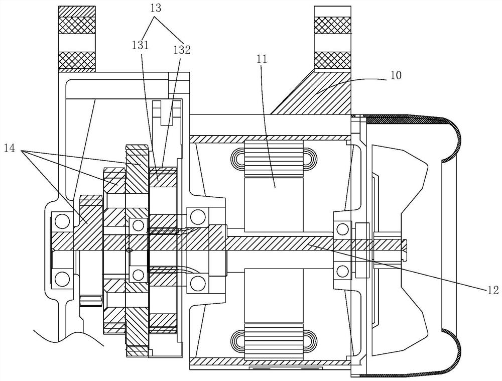
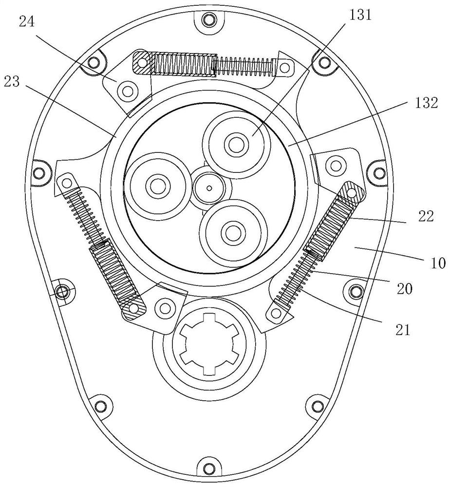
[0011] example, see Figure 1 to Figure 2 Shown: a power output mechanism on a battery car, including an outer casing 10, on the outer casing 10 there is an output motor 11, a power shaft 12, a planetary gear assembly 13, a power output gear assembly 14 and a power storage / release device, the output motor 11 is a brushless motor. One end of the power shaft 12 is connected to the output motor 11, and the other end is connected to the power output gear assembly 14. The power shaft 12 is formed with external teeth, which mesh with the planetary gear assembly 13 for transmission, so that , when the power shaft 12 rotates, the power output gear assembly 14 and the planetary gear assembly 13 will rotate together w...


PUM


Abstract

The invention discloses a power output mechanism on a battery car, which comprises an outer shell, the outer shell is provided with an output motor, a power rotating shaft, a planet wheel assembly, a power output gear assembly and a power storage / release device, one end of the force storage / release device is connected with the power output gear assembly, the other end of the force storage / release device is connected with the power output gear assembly and is in meshing transmission with the planet wheel assembly through outer teeth, the planet wheel assembly is connected with the power output gear assembly through a connecting shaft, and the force storage / release device comprises a force storage / release spring, a spring positioning shaft, a spring sleeve and a gear sleeve; a fixed lug is formed on the peripheral face of the gear sleeve, the spring positioning shaft is hinged to the fixed lug, the peripheral face of the spring positioning shaft is sleeved with the force storage / release spring, one end of the force storage / release spring abuts against the fixed lug, and the other end of the force storage / release spring abuts against a step in the spring sleeve. A spring sleeve is positioned within the outer housing. The device has the advantages that power loss and waste cannot be caused in the using process, and meanwhile tire abrasion can be avoided.

Description

technical field [0001] The invention belongs to the technical field of components on a battery car, and in particular relates to a power output mechanism on a battery car. Background technique [0002] At present, the power output mechanism of the battery car is generally powered by a brushless motor. There is a Hall element inside the brushless motor. After the Hall element detects a signal, the controller can supply power or cut off the brushless motor. The advantage of the Hall element is that the vehicle has better stability during operation, but the disadvantage is that it is easily damaged by external forces during use; the brushless motors without Hall are commonly used in the existing battery cars. , although it avoids the problem that the Hall element is easily damaged, but when the vehicle starts, the motor needs to rotate 120° to measure the phase, so that the controller can know which line to supply power. This method is in some special cases, such as uphill sect...

Claims


Application Information

Patent Timeline
Patent Type & Authority Applications(China)
IPC IPC(8): F16H33/06
CPCF16H33/06
Inventor 陶翊彪
Owner 浙江无懈电机有限公司
Why Eureka
Try Eureka