Seal welding device for quartz crystal resonator wafer

A quartz crystal and resonator technology, applied in the field of quartz crystal resonator wafer processing, can solve the problems of sealing and welding quality impact, metal debris scattering, metal debris splashing, etc., to achieve the effect of ensuring the quality of removal and convenient cleaning

Pending Publication Date: 2022-07-29
江苏奥斯力特电子科技有限公司
View PDF0 Cites 0 Cited by
  • Summary
  • Abstract
  • Description
  • Claims
  • Application Information

AI Technical Summary

Problems solved by technology

[0004] The purpose of the present invention is to solve the problem that the welding and melting metal debris splashes easily when the sealing welding device of the quartz crystal resonator wafer in the prior art is sealing and welding the quartz crystal resonator wafer, and the splashed metal debris is scattered. On the surface of the subsequent quartz crystal resonator wafer to be sealed and wel

Method used


Image

  • Seal welding device for quartz crystal resonator wafer
  • Seal welding device for quartz crystal resonator wafer
  • Seal welding device for quartz crystal resonator wafer

Examples


Example Embodiment

[0037] Example 1

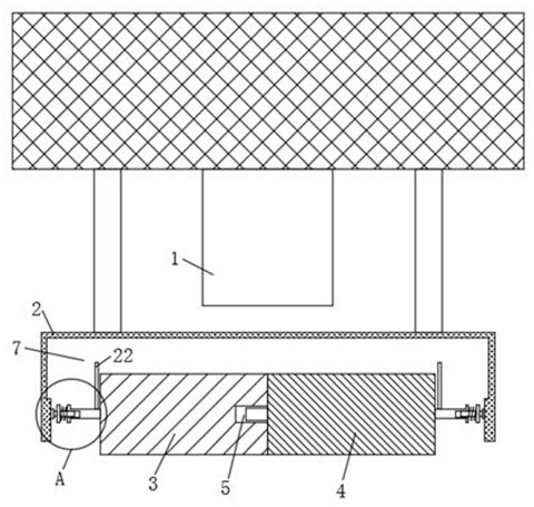
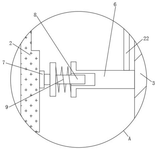
[0038] refer to Figure 1-Figure 10, a sealing and welding device for a quartz crystal resonator chip, comprising a sealing and welding device body 1, a fixed shell 2 is fixedly installed at the lower end of the sealing and welding device body 1, and a sticking roller 3 is provided on the left side of the fixed shell 2. The sticking roller There is a sticking roller 24 on the right side of the first 3, and the middle part of the right end of the sticking roll 1 3 is provided with a slot 5 corresponding to the sticking roll 2 4. The two rollers 4 are attached, and the ends of the sticking rollers 1 3 and the sticking rollers 2 4 are fixedly installed with the rotating shaft 6, and the one end of the rotating shaft 6 that is far away from each other is inserted with an insert rod 8, and the end of the sticking rod 8 that is far away from each other is inserted. Bearings 7 are fixedly installed, and the ends of the bearings 7 away from each other are fixedly i...

Example Embodiment

[0039] Embodiment 2

[0040] refer to Figure 1-Figure 10 , In this embodiment, it is basically the same as the first embodiment, and it is more optimized that a clearing plate 10 is provided on the front side of the sticking roller one 3 and sticking roller two 4, and the clearing plate 10 is connected with sticking roll one 3 and sticking roll two 4. The lower end of the clearing plate 10 is fixedly installed with a connecting plate 11, the front end of the connecting plate 11 is symmetrically fixed with a telescopic rod 12, the front end of the telescopic rod 12 is fixedly installed on the fixed shell 2, and the telescopic rod 12 is fixed on the A spring two 13 is sleeved, and the front and rear ends of the spring two 13 are fixedly installed on the fixed shell 2 and the connecting plate 11 respectively. There is a baffle 15, the lower end of the clearing plate 10 is fixedly installed with a limit clip 16 corresponding to the baffle 15, and the baffle 15 runs through the l...

Example Embodiment

[0041] Embodiment 3

[0042] refer to Figure 1-Figure 10 , in this embodiment, it is basically the same as the first embodiment, and it is more optimized that a plurality of air outlet holes 23 are opened inside the cleaning plate 10, and one end of the connection pipe 24 is fixedly installed at the lower end of the air outlet hole 23, and the other end of the connection pipe 24 is installed. An air cylinder 25 is communicated with, the air cylinder 25 is fixedly installed on the support plate 19, the rear end of the air cylinder 25 is inserted with a piston 26, and the rear end of the piston 26 is fixedly installed on the pressing plate 20; during use, and the pressing plate 20 moves forward. It will drive the piston 26 to move forward, and the piston 26 squeezes the gas in the gas cylinder 25 out through the connecting pipe 24 and the gas outlet 23. The debris is accumulated inside the cleaning plate 10 , so that the debris can be easily discharged from the discharge openi...


PUM


Abstract

A quartz crystal resonator wafer sealing and welding device disclosed by the present invention comprises a sealing and welding device body, the lower end of the sealing and welding device body is fixedly provided with a fixed shell, the left side in the fixed shell is provided with an adhesive roller I, the right side of the adhesive roller I is provided with an adhesive roller II, and the ends, far away from each other, of the adhesive roller I and the adhesive roller II are fixedly provided with rotating shafts; inserting rods are inserted into the ends, away from each other, of the rotating shafts, the inserting rods are sleeved with first springs, clearing plates are arranged on the front sides of the first sticking roller and the second sticking roller, the clearing plates are attached to the surfaces of the first sticking roller and the second sticking roller, and connecting plates are fixedly installed at the lower ends of the clearing plates. When the quartz crystal resonator wafer surface seal welding device is used, the arranged first adhesive roller and the arranged second adhesive roller are attached to the surface of a quartz crystal resonator wafer, metal chippings sputtered when the surface of the quartz crystal resonator wafer is subjected to seal welding can be conveniently cleaned, the situation that the chippings remain on the subsequent surface of the quartz crystal resonator wafer is avoided, and the service life of the quartz crystal resonator wafer is prolonged. And the sealing and welding quality of the quartz crystal resonator wafer is influenced.

Description

technical field [0001] The invention relates to the technical field of quartz crystal resonator wafer processing, in particular to a sealing and welding device for a quartz crystal resonator wafer. Background technique [0002] Quartz crystal resonator, referred to as quartz crystal or crystal oscillator, is an electronic component that uses the piezoelectric effect of quartz crystal (also known as crystal) to generate high-precision oscillation frequency, and belongs to passive components. The component is mainly composed of quartz wafer, base, shell, silver glue, silver and other components. According to the lead condition, it can be divided into two types: in-line (with lead) and surface mount (without lead). [0003] In the prior art, when a sealing and welding device for a quartz crystal resonator chip seals and welds a quartz crystal resonator chip, the molten metal debris is prone to splashing, and the splashed metal debris is scattered in the subsequent sealing and ...

Claims


Application Information

Patent Timeline
IPC IPC(8): B23K37/00B08B1/00B08B5/02
CPCB23K37/00B08B1/00B08B5/02
Inventor 唐志强
Owner 江苏奥斯力特电子科技有限公司
Why Eureka
Try Eureka