
Self-adaptive chamfering and drilling equipment for sliding bearing

A technology for sliding bearings and drilling equipment, applied in metal processing equipment, other manufacturing equipment/tools, supports, etc., can solve problems such as adjustment troubles, increase friction coefficient, and reduce processing efficiency, so as to reduce the number of replacement or maintenance, The effect of reducing the cost of use and improving maintenance efficiency

Pending Publication Date: 2022-07-29
JIASHAN THREE STAR BEARING
View PDF23 Cites 2 Cited by
  • Summary
  • Abstract
  • Description
  • Claims
  • Application Information

AI Technical Summary

Problems solved by technology

[0004] 1. The through hole drilled by the existing drill bit is usually perpendicular to the axis of the bearing pad. When the wall thickness of the bearing pad is small, the inner wall interface of the through hole is small, so the solid lubricant applied inside will also be reduced, thus increasing the friction coefficient , the shaft sleeve wears more seriously and needs frequent replacement or maintenance
[0005] 2. Ordinary lathes usually use a manually operated three-jaw chuck to clamp the bushing, which reduces the clamping efficiency of the bushing, and there is a shaking problem when the bushing is chamfered, which greatly reduces the processing efficiency
[0006] 3. The turning angle of conventional turning tools is fixed, and it is very troublesome to adjust, so the slope of the chamfer cannot be quickly adjusted according to the needs of use, and the processing requirements of chamfers with different slopes cannot be met, which reduces the practicability

Method used


Image

  • Self-adaptive chamfering and drilling equipment for sliding bearing
  • Self-adaptive chamfering and drilling equipment for sliding bearing
  • Self-adaptive chamfering and drilling equipment for sliding bearing

Examples


Embodiment Construction

[0040] The technical solutions of the present invention are further described below with reference to the accompanying drawings and through specific embodiments.

[0041] Among them, the accompanying drawings are only used for exemplary description, and they are only schematic diagrams, not physical drawings, and should not be construed as restrictions on this patent; in order to better illustrate the embodiments of the present invention, some parts of the accompanying drawings will be omitted, Enlarged or reduced, does not represent actual product size.

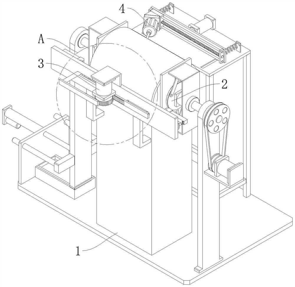
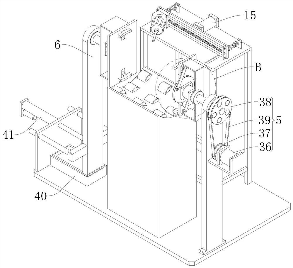
[0042] An adaptive chamfering drilling equipment for sliding bearings, comprising a base and a material table 1, the material table 1 is fixedly arranged on the top of the base,

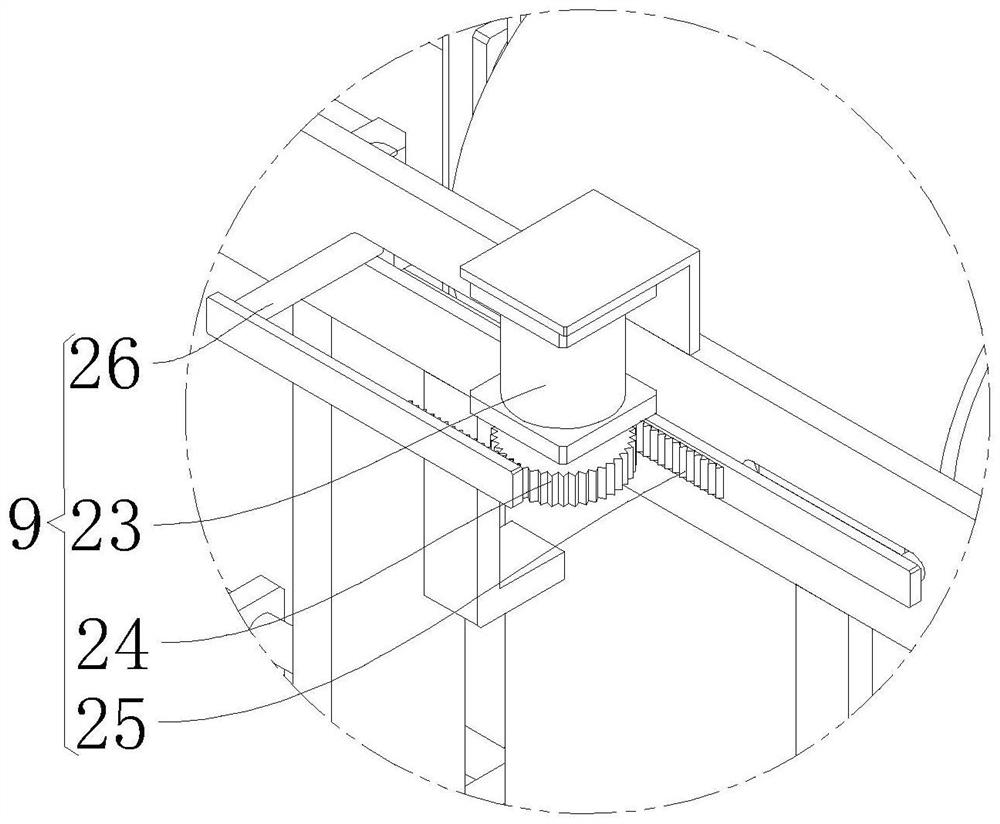
[0043] Also includes a controller, a clamping mechanism 2, a chamfering mechanism 3 and a drilling mechanism 4,

[0044] The clamping mechanism 2 is provided on the top of the base to clamp the sliding bearing. The clamping mechanism 2 includes a ...


PUM


Abstract

The invention relates to the technical field of sliding bearing machining, in particular to sliding bearing self-adaptive chamfering and drilling equipment which comprises a base and a material table and further comprises a controller, a clamping mechanism, a chamfering mechanism and a drilling mechanism. The chamfering mechanism comprises a driving assembly, two sliding plates, two turning tools and two angle adjusting assemblies, the drilling mechanism comprises a drill bit, a mounting table, a pushing assembly and a sliding assembly, the sliding assembly is arranged on the pushing assembly, and the drill bit is fixedly arranged on the sliding assembly; the rotating assembly, the driving assembly, the pushing assembly and all the angle adjusting assemblies are electrically connected with the controller, according to the self-adaptive chamfering drilling equipment for the sliding bearing, it can be prevented that the amount of solid lubricant embedded into the through hole is small through oblique drilling, then abrasion between a shaft sleeve and a shaft cover is reduced, and the service life of the shaft sleeve and the shaft cover is prolonged. The replacement or maintenance frequency of the sliding bearing is reduced, the use cost is reduced, and the maintenance efficiency is improved.

Description

technical field [0001] The invention relates to the technical field of sliding bearing processing, in particular to a self-adaptive chamfering drilling device for sliding bearings. Background technique [0002] Sliding bearings, bearings that work under sliding friction. Sliding bearings work smoothly, reliably and without noise. Under liquid lubrication conditions, the sliding surfaces are separated by lubricating oil without direct contact, which can greatly reduce friction loss and surface wear, and the oil film also has a certain ability to absorb vibration. But the starting friction resistance is large. The part of the shaft supported by the bearing is called the journal, and the part that matches the journal is called the bearing pad. The bearing pad has two types: integral type and split type. The wall is used to apply solid lubricating material to reduce bearing wear and improve service life. At the same time, both ends of the shaft sleeve need to be chamfered to ...

Claims


Application Information

Patent Timeline
Patent Type & Authority Applications(China)
IPC IPC(8): B23P23/02B23Q3/00B23Q5/34B23Q5/40
CPCB23P23/02B23Q3/00B23Q5/34B23Q5/40B23Q2703/10
Inventor 钱咬法
Owner JIASHAN THREE STAR BEARING
Learn More