
Manufacturing and machining device for alloy accessories of numerical control machine tool

A technology of CNC machine tools and processing devices, which is applied in the direction of manufacturing tools, metal processing equipment, and grinding machine parts, etc., which can solve the problem of low deburring flexibility, inability to adapt the grinding tool to the tooth groove, and low deburring efficiency and other issues to achieve the effect of improving flexibility, precise adjustment and improving efficiency

Inactive Publication Date: 2022-07-29
新沂蓝西特制造有限公司
View PDF0 Cites 0 Cited by
  • Summary
  • Abstract
  • Description
  • Claims
  • Application Information

AI Technical Summary

Problems solved by technology

[0003] There are still some deficiencies in the actual use of the bevel gear deburring equipment in the alloy parts of CNC machine tools. The gears are deburred. When facing multiple different bevel gears, the deburring abrasives need to be replaced frequently, and the deburring efficiency is low.
[0004] 2. The abrasive tools assembled on the existing bevel gear deburring equipment can only deburr the same kind of tooth grooves. When facing bevel gears with the same tooth groove shape but different tooth groove sizes, the abrasive tools cannot be deburred. Adaptive adjustment to the cogging, low flexibility for deburring

Method used


Image

  • Manufacturing and machining device for alloy accessories of numerical control machine tool
  • Manufacturing and machining device for alloy accessories of numerical control machine tool
  • Manufacturing and machining device for alloy accessories of numerical control machine tool

Examples


Embodiment Construction

[0028] Embodiments of the present invention are described in detail below with reference to the accompanying drawings, but the present invention can be implemented in many different ways as defined and covered by the claims.

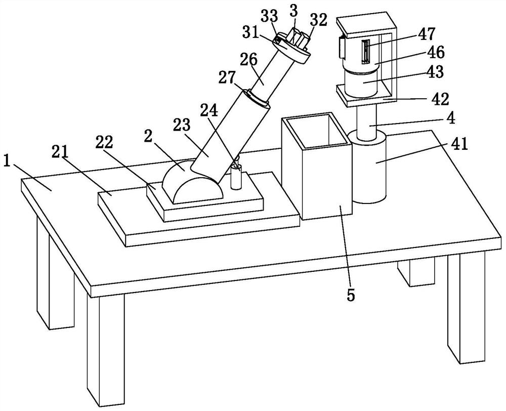
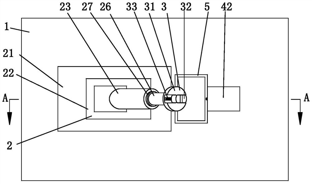
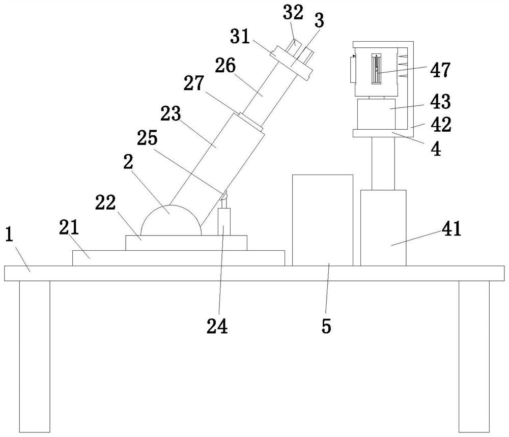
[0029] see figure 1 , figure 2 and image 3 , a CNC machine tool alloy parts manufacturing and processing device, including a support table 1, a positioning assembly 2, a fixed assembly 3, a grinding assembly 4 and a waste collection frame 5, the support table 1 is placed on the ground, and the upper end surface of the support table 1 A positioning assembly 2 is fixedly connected, the upper end of the positioning assembly 2 is fixedly connected with a fixing assembly 3, the upper end surface of the support table 1 is fixedly connected with a grinding assembly 4, and the upper end surface of the support table 1 is connected with a waste scrap collection frame 5. The bottom of the inner surface of the chip collection frame 5 is provided with a magnetic ...


PUM


Abstract

The invention relates to the field of machine tool accessory manufacturing and machining, in particular to a numerical control machine tool alloy accessory manufacturing and machining device. Comprising a supporting table, a positioning assembly, a fixing assembly, a grinding assembly and a scrap collecting frame, the supporting table is placed on the ground, the positioning assembly is fixedly connected to the upper end face of the supporting table, the fixing assembly is fixedly connected to the upper end of the positioning assembly, the grinding assembly is fixedly connected to the upper end face of the supporting table, and the scrap collecting frame is connected to the upper end face of the supporting table. The problems that when existing bevel gear deburring equipment faces multiple different bevel gears, deburring grinding tools need to be frequently replaced, and the deburring efficiency is low are solved. According to the deburring device, the grinding tool barrel and other structures are arranged, the grinding tool barrel is provided with the multiple grinding tool mechanisms, the grinding motor drives the cam to eject the grinding tool mechanisms out of the grinding tool barrel, the other grinding tool mechanisms are hidden in the grinding tool barrel, and therefore automatic replacement of the deburring grinding tool is achieved, and the deburring efficiency is improved.

Description

technical field [0001] The invention relates to the field of manufacturing and processing of machine tool parts, in particular to a manufacturing and processing device for alloy parts of numerically controlled machine tools. Background technique [0002] Alloy accessories refer to the parts or components of assembling machinery. Alloy accessories can be divided into standard accessories and optional accessories. Standard accessories refer to the structure, size, drawing, marking and other aspects that have been completely standardized and produced by professional factories. Parts, commonly used accessories are threaded parts, keys, pins, bearings, gears, etc. [0003] Bevel gear deburring equipment in CNC machine tool alloy accessories still has some deficiencies in actual use. The specific deficiencies are: 1. Most of the existing bevel gear deburring equipment can only be equipped with one kind of deburring abrasive tool for bevel The gear is deburred, and the deburring a...

Claims


Application Information

Patent Timeline
IPC IPC(8): B24B9/04B24B27/02B24B41/04B24B47/22
CPCB24B9/04B24B27/02B24B47/22B24B41/04
Inventor 王大向
Owner 新沂蓝西特制造有限公司
Learn More