Communication optical fiber testing method

An optical fiber testing and communication technology, applied in the field of optical fiber production, can solve the problems of cumbersome testing process, and achieve the effect of improving efficiency, saving operating procedures, and improving versatility

Pending Publication Date: 2022-07-29
杜银平
View PDF0 Cites 0 Cited by
  • Summary
  • Abstract
  • Description
  • Claims
  • Application Information

AI Technical Summary

Problems solved by technology

[0003] Optical fibers are affected by many influences during use, such as bending, stretching, twisting, and temperature. Therefore, it is usually necessary to test the influence of these effects on optical fib

Method used


Image

  • Communication optical fiber testing method
  • Communication optical fiber testing method
  • Communication optical fiber testing method

Examples


Example Embodiment

[0029] Example 1

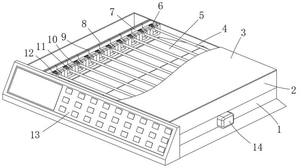
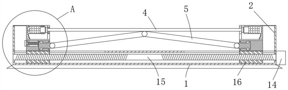
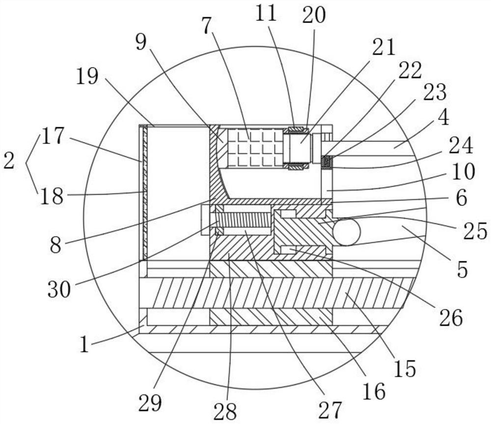
[0030] refer to Figure 1-5 , a communication optical fiber testing device, comprising a bottom case 1, an operation panel 13 is provided on one side of the bottom case 1, a support block 28 is provided on both sides of the top outer wall of the bottom case 1, and a drive mechanism is provided inside the bottom case 1 , the top outer walls of the two support blocks 28 are provided with a transverse block 8, and one side inner wall of the transverse block 8 is slidably connected with a damping slider 9, and one side outer wall of the two damping sliders 9 is fixedly connected to the light receiver 7 respectively. And the optical transmitter, the optical receiver 7 and the outer wall of one side of the optical transmitter are fixedly connected with a vertical plate 20, wherein the lateral outer wall of one vertical plate 20 is provided with evenly distributed first interface slots, and the lateral outer wall of the other vertical plate 20 is provided with The...

Example Embodiment

[0039] Example 2

[0040] A communication optical fiber testing method, using the communication optical fiber testing device described in Embodiment 1, the steps are as follows:

[0041] A, initial value measurement: insert the optical fiber connector 21 into the first interface slot and the interface slot 32 on both sides respectively, the optical fiber 4 is in a straight state, the pressure sensor 23 measures the pressure to zero, the optical transmitter sends out an optical signal, and passes through the optical fiber. 4 After transmission, the optical receiver 7 accepts the optical signal strength as the initial value;


PUM


Abstract

The invention belongs to the technical field of optical fiber production, and particularly relates to a communication optical fiber testing method and a used testing device.The communication optical fiber testing device comprises a bottom shell, an operation panel is arranged on one side of the bottom shell, supporting blocks are arranged on the two sides of the outer wall of the top of the bottom shell, a driving mechanism is arranged in the bottom shell, and transverse blocks are arranged on the outer walls of the tops of the two supporting blocks; and damping sliding blocks are slidably connected to the inner wall of one side of the transverse block, a light receiver and a light emitter are fixedly connected to the outer walls of one sides of the two damping sliding blocks correspondingly, and vertical plates are fixedly connected to the outer walls of one sides of the light receiver and the light emitter correspondingly. According to the invention, the influence of the bending degree, the tensile degree, the torsion degree and the temperature on the optical fiber can be measured through the movement of the moving block and the rotation of the shifting ring, so that the multifunctionality of the device can be improved, the operation procedure of the optical fiber test is saved, the optical fiber test efficiency is improved, fine adjustment can be carried out through the adjusting screw, and the measurement accuracy is improved.

Description

technical field [0001] The invention relates to the technical field of optical fiber production, in particular to a communication optical fiber testing device and a testing method thereof. Background technique [0002] Optical fiber is short for optical fiber. It is a fiber made of glass or plastic, which can be used as a light transmission tool. The tiny optical fiber is encapsulated in a plastic sheath, so that it can be bent without breaking. The transmitting device uses a light-emitting diode or a laser to transmit the light pulse to the optical fiber, and the receiving device at the other end of the optical fiber detects the pulse using a photosensitive element. In daily life, the conduction loss of light in the optical fiber is lower than the conduction loss of electricity in the wire Much more, optical fibers are used for long distance information transfer. [0003] Optical fibers are affected by many influences during use, such as bending, stretching, twisting and t...

Claims


Application Information

Patent Timeline
IPC IPC(8): G01M11/02
CPCG01M11/0214G01M11/0207
Inventor 杜银平
Owner 杜银平
Why Eureka
Try Eureka