3D detection method for computer rear shell

A detection method and 3D technology, applied in image analysis, instruments, calculations, etc., can solve the problems of increasing algorithm data processing volume, increasing detection cost, low detection accuracy, etc., to improve the speed of algorithm processing, improve dynamic repeatability, The effect of accurate detection results

Active Publication Date: 2022-07-29
SUZHOU DINNAR TECH FOR AUTOMATION CO LTD
View PDF4 Cites 2 Cited by
  • Summary
  • Abstract
  • Description
  • Claims
  • Application Information

AI Technical Summary

Problems solved by technology

[0002] In the 3C digital field, due to the influence of manufacturing technology and environment, the size and flatness of the computer back shell may be different from the standard, which directly affects product assembly and customer experience
Traditional detection usually uses manual detection, which is slow in detection speed, low in precision, easy to fatigue, and high in labor costs for detection, which can no longer meet the requirements of modern production.
[0003] In the prior art, 3D full-scan inspection of the backplane is usually used instead of manual inspection. Although it can detect the size and flatness of the computer backplane, there are still some problems in the use process: due to the size of the computer backplane Relatively large, when using 3D full-scan detection, the detection process takes a long time, and a lot of unnecessary area data is obtained, which increases the data processing amount of the algorithm, making the algorithm take a long time and the workload is very heavy ;The splicing accuracy is low in the process of pattern splicing, which is prone to detection errors and affects the detection results; if the detection speed needs to be adjusted, one method is to increase the scanning distance, which will reduce the detection accuracy; another method requires 3D full scanning Replacement of testing equipment with higher-precision testing equipment increases testing costs
[0004] Therefore, to develop a 3D detection method for the computer rear case, by calibrating the 2D camera and the 3D laser camera and obtaining the 3D data of the ROI, can solve the problems of slow detection speed, low splicing accuracy, low detection accuracy, The algorithm takes a long time to deal with the problem and realizes high-speed and high-precision 3D detection, which obviously has practical practical significance

Method used


Image

  • 3D detection method for computer rear shell
  • 3D detection method for computer rear shell
  • 3D detection method for computer rear shell

Examples


Embodiment 1

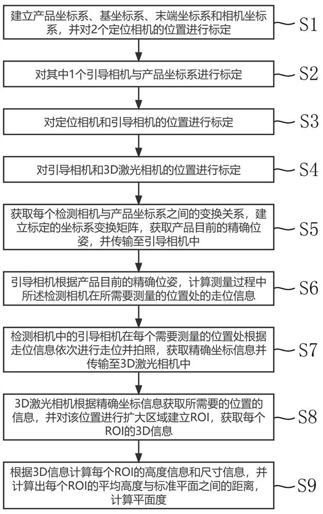
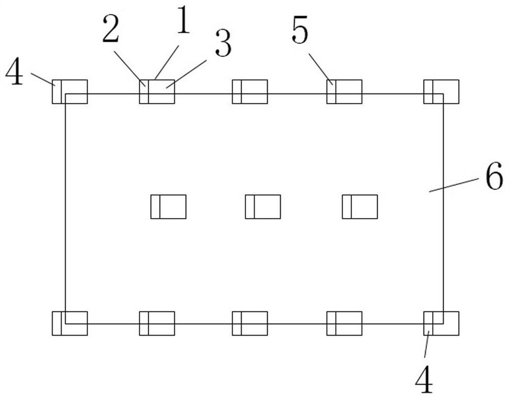
[0061] like Figure 1-Figure 2 As shown, this embodiment relates to a 3D detection method for a computer back case, including a manipulator and several groups of detection cameras 1 , each group of detection cameras 1 includes a 2D camera 2 and a 3D laser camera 3 ; The 2D camera 2 is set as the positioning camera 4, and the 2D camera 2 in the other detection cameras 1 is set as the guidance camera 5; specifically, the following steps are included:

[0062] S1. Establish a product coordinate system, a base coordinate system, an end coordinate system and a camera coordinate system, and calibrate the positions of the two positioning cameras 4;

[0063] S2, calibrating one of the guide cameras 5 and the product coordinate system;

[0064] S3, calibrating the positions of the positioning camera 4 and the guiding camera 5;

[0065] S4, calibrating the positions of the guidance camera 5 and the 3D laser camera 3;

[0066] S5. After the calibration in steps S1-S4, obtain the trans...


PUM


Abstract

The invention discloses a 3D detection method for a computer rear shell, which comprises a manipulator and a plurality of groups of detection cameras, and each group of detection cameras comprises a 2D camera and a 3D laser camera; calibrating the 2D camera, the 3D laser camera and the manipulator, and establishing a calibrated coordinate system transformation matrix; the 2D camera obtains accurate coordinate information, the 3D laser camera establishes ROIs according to the accurate coordinate information, and 3D information of each ROI is obtained; and calculating height information and size information of each ROI according to the 3D information, and calculating the flatness. Positioning is carried out through the 2D camera, calibration is carried out on the 2D camera, the manipulator and the 3D laser camera in three aspects, and the positioning precision is higher; the ROI is detected and compared with the fitted standard plane, so that the data volume is reduced, the detection speed is increased, and the detection precision is improved.

Description

technical field [0001] The invention relates to the technical field of machine vision, in particular to a 3D detection method of a computer back shell. Background technique [0002] In the field of 3C digital, due to the influence of manufacturing technology and environment, the size and flatness of the computer back shell may be different from the standard, which directly affects the product assembly and customer experience. The traditional detection is usually manual detection, which is slow in detection speed, low in precision, and easily fatigued by manual labor. [0003] In the prior art, the backplane 3D full scan inspection is usually used instead of manual inspection. Although it can detect the size and flatness of the computer backplane, there are still some problems in the use process: due to the size of the computer backplane It is relatively large. When 3D full scan detection is used, the detection process takes a long time, and many unnecessary regional data ar...

Claims


Application Information

Patent Timeline
Patent Type & Authority Applications(China)
IPC IPC(8): G06T7/80G06T7/73
CPCG06T7/85G06T7/75G06T2207/20104G06T2207/30244
Inventor 韩冲冲徐飞郑林秦应化
Owner SUZHOU DINNAR TECH FOR AUTOMATION CO LTD
Why Eureka
Try Eureka