
Circularly polarized microstrip antenna with broadband, high gain and low axial ratio

A microstrip antenna, high-gain technology, applied in antennas, resonant antennas, antenna components, etc., can solve the problems of bandwidth, gain and axial ratio can not be taken into account at the same time, to achieve stable gain in the band, low axial ratio, wide frequency bandwidth Effect

Pending Publication Date: 2022-07-29
北京合众卫通科技有限公司
View PDF0 Cites 0 Cited by
  • Summary
  • Abstract
  • Description
  • Claims
  • Application Information

AI Technical Summary

Problems solved by technology

[0003] The purpose of the present invention is to overcome the deficiencies in the prior art, to provide a circularly polarized microstrip antenna with novel structure design, high gain and low axial ratio, which solves the problems of bandwidth, gain and axial ratio in the current circularly polarized microstrip antenna. Issues that cannot be addressed at the same time

Method used


Image

  • Circularly polarized microstrip antenna with broadband, high gain and low axial ratio
  • Circularly polarized microstrip antenna with broadband, high gain and low axial ratio
  • Circularly polarized microstrip antenna with broadband, high gain and low axial ratio

Examples


Embodiment Construction

[0018] Below in conjunction with accompanying drawing and embodiment, the present invention is further described:

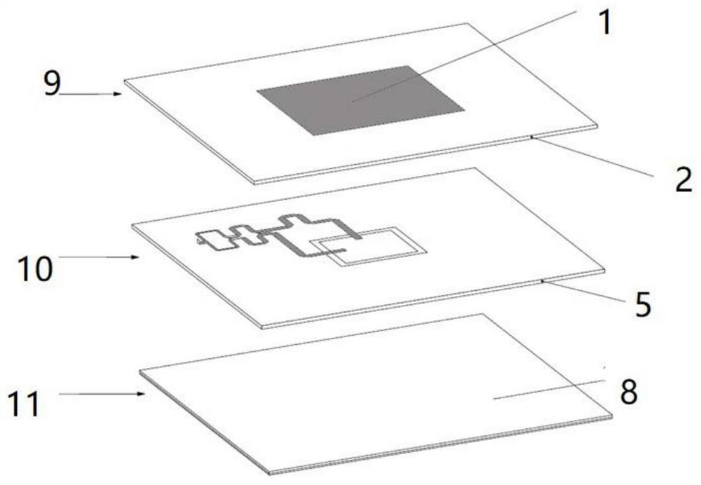
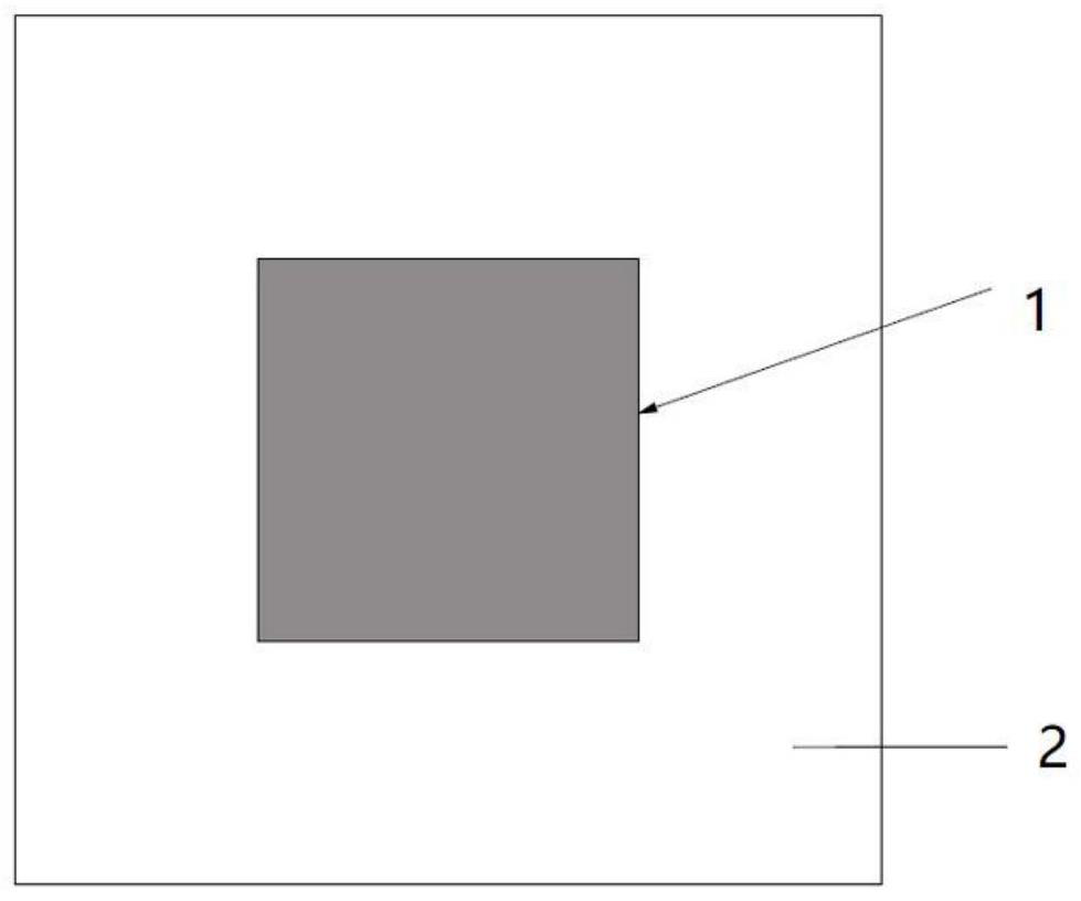
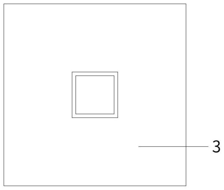
[0019] according to Figure 1-Figure 6 The embodiment discloses a wide-band, high-gain, low-axis-ratio circularly polarized microstrip antenna, including a square resonant patch A1, a slot layer B1, a 1.85GHz broadband Wilkinson phase-shifting power divider B2, a metal surface reflection For the laminated structure formed by plate C, dielectric substrate A and dielectric substrate B, the dielectric substrates are all FR4 dielectric plates; the metal surface reflector C is copper plate.

[0020] The composition of the whole invention is as follows from top to bottom: square resonant patch A1, dielectric substrate A, among which, square resonant patch A1 is etched on the top layer of dielectric substrate A, gap layer B1, dielectric substrate B, 1.85GHz broadband Weir Kinsen phase-shifting power divider B2, in which the gap layer B1 is etched on the top layer of di...


PUM


Abstract

The invention discloses a broadband high-gain low-axial-ratio circularly polarized microstrip antenna which is formed by stacking a first layer, a second layer and a third layer from top to bottom, the first layer comprises a square resonance patch A1 and a dielectric substrate A, the square resonance patch A1 is etched on the top layer of the dielectric substrate A, the second layer comprises a gap layer B1, a dielectric substrate B and a 1.85 GHz broadband Wilkinson phase-shifting power divider B2, and the dielectric substrate B is etched on the top layer of the dielectric substrate A; the slot layer B1 is located at the top layer of the dielectric substrate B, and the 1.85 GHz broadband Wilkinson phase-shifting power divider B2 is located at the bottom layer of the dielectric substrate B. According to the circularly polarized microstrip antenna, the gain of more than 6dBi and the axial ratio of less than 3dB can be realized in the bandwidth, the problem that the bandwidth, the gain and the axial ratio in the current circularly polarized microstrip antenna cannot be considered at the same time is solved, and the antenna has the advantages of wide frequency band, high gain, low axial ratio, simple structure and the like; the method is suitable for the wireless communication fields of electronic countermeasure, radio frequency identification, satellite navigation, remote sensing monitoring and the like.

Description

technical field [0001] The invention relates to the technical field of communication antennas, in particular to a circularly polarized microstrip antenna with a wide frequency band, high gain and low axial ratio in the frequency band of 1.5GHz-2.2GHz. Background technique [0002] With the rapid development of the information age, satellite navigation, positioning and communication systems have been more and more widely used in the military and civilian fields, and have played an increasingly important role. Wireless communication systems require more and more antenna radiation stability. In order to quickly and accurately capture weak satellite signals, the antenna is generally required to have a wide frequency bandwidth and maintain a certain high gain. Most of the current relatively mature circularly polarized antenna solutions have the problem that high gain and broadband cannot be taken into account at the same time, while broadband and high-gain linearly polarized ante...

Claims


Application Information

Patent Timeline
Patent Type & Authority Applications(China)
IPC IPC(8): H01Q1/00H01Q1/24H01Q5/10H01Q5/20H01Q9/04
CPCH01Q1/002H01Q9/0428H01Q9/0414H01Q5/20H01Q5/10H01Q1/241
Inventor 赵恒勇申扎平
Owner 北京合众卫通科技有限公司
Learn More