Electric push rod

An electric push rod and rod body technology, which is applied to circuits, electrical components, coupling devices, etc., can solve the problems of complex electrical connection structure, inconvenient assembly, and many welding processes, so as to facilitate assembly, simplify structure and process, and increase contact. area effect

Inactive Publication Date: 2022-07-29
HUIZHOU UPSPRINGIN TELLIGENT TECH CO LTD
View PDF0 Cites 0 Cited by
  • Summary
  • Abstract
  • Description
  • Claims
  • Application Information

AI Technical Summary

Problems solved by technology

[0004] In order to overcome at least one of the above-mentioned defects in the prior art, the present invention provides an electric push rod with a simpler structure and more convenient assembly, so as to solve the problem of complex electrical connection structure and welding process when powering the motor in the prior art. Many, inconvenient assembly problems

Method used


Image

  • Electric push rod
  • Electric push rod
  • Electric push rod

Examples


Embodiment Construction

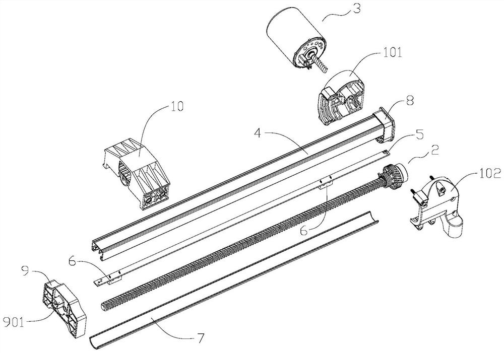
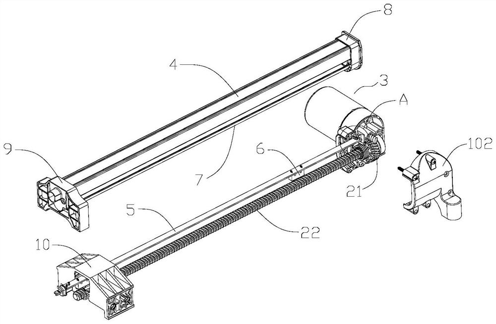
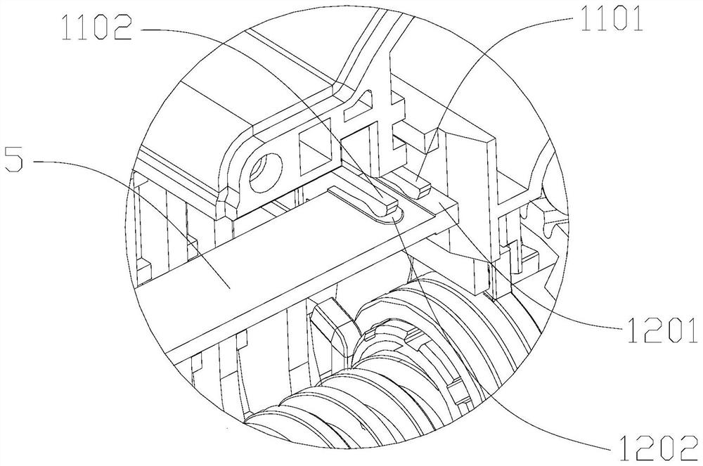
[0049] For better understanding and implementation, the technical solutions in the embodiments of the present invention will be clearly and completely described below with reference to the accompanying drawings in the embodiments of the present invention.

[0050] In the description of the present invention, it should be noted that the terms "upper", "lower", "front", "rear", "left", "right", "vertical", "horizontal", "top", The orientation or positional relationship indicated by "bottom", "inner", "outer", etc. is based on the orientation or positional relationship shown in the accompanying drawings, and is only for the convenience of describing the present invention and simplifying the description, rather than indicating or implying the indicated device or Elements must have a particular orientation, be constructed and operate in a particular orientation and are therefore not to be construed as limitations of the invention.

[0051] Unless otherwise defined, all technical an...


PUM


Abstract

The invention discloses an electric push rod which comprises a mounting seat, a transmission assembly arranged on the mounting seat and a motor arranged on the mounting seat and in transmission connection with the transmission assembly, and the motor is electrically connected with a conductive part. In addition, the motor further comprises a rod body, one end of the rod body is connected to the mounting base, a rigid PCB is arranged in the rod body, one end of the rigid PCB extends into the mounting base, a power connection part is arranged on the rigid PCB, and the power connection part abuts against the conductive piece so that the motor can be electrically connected with the rigid PCB. Therefore, the rigid PCB is adopted to replace a traditional flexible PCB, the power connection part is arranged on the rigid PCB, and the original welding procedure between the flexible PCB and the power line is omitted; besides, when the motor is connected to the mounting seat and the mounting seat is connected to one end of the rod body, the conductive piece of the motor can abut against the power connection part on the rigid PCB, then electrical connection between the motor and the rigid PCB is achieved, the structure and process of electrical connection between the motor and the rigid PCB are simplified, and the overall structure of the electric push rod is simplified.

Description

technical field [0001] The invention relates to the technical field of mechanical equipment, in particular to an electric push rod. Background technique [0002] The electric push rod is a linear drive device, which mainly uses the screw nut drive to convert the rotary motion of the motor into the linear motion of the slider. It can be used as an executive machine in various simple or complex technological processes to achieve long-distance control, centralized control or automatic control. At present, electric actuators have been widely used in electric medical beds, electric sofas, electric booth lifting rods, industrial electric lifting systems, etc. [0003] In order to supply power to the motor in the electric push rod, there are mainly two ways to achieve it: the first is to set a power cord in the motor, one end of the power cord is electrically connected to the motor, and the other end is led out through the lead wire assembly and connected to the motor. Electrical...

Claims


Application Information

Patent Timeline
Patent Type & Authority Applications(China)
IPC IPC(8): H01R12/71H01R13/40H01R13/629H01R13/502
CPCH01R12/71H01R13/40H01R13/629H01R13/502
Inventor 齐发云孙泽明彭作超唐大专李子龙
Owner HUIZHOU UPSPRINGIN TELLIGENT TECH CO LTD
Why Eureka
Try Eureka