Power equipment cooling device

A technology for power equipment and cooling devices, which is applied in the directions of substation/distribution device housing, seismic equipment, and substation/switchgear cooling/ventilation. , reduce the service life of electrical equipment and other issues, to achieve the effect of improving service life, ensuring close contact, and ensuring normal work

Pending Publication Date: 2022-07-29
STATE GRID SHANDONG ELECTRIC POWER CO PINGYUAN POWER SUPPLY CO +1
View PDF0 Cites 0 Cited by
  • Summary
  • Abstract
  • Description
  • Claims
  • Application Information

AI Technical Summary

Problems solved by technology

[0002] Power equipment mainly includes power generation equipment and power supply equipment. Power generation equipment is mainly power plant boilers, steam turbines, gas turbines, water turbines, generators, transformers, etc. Power supply equipment is mainly transmission lines of various voltage levels, transformers, contactors, etc. In daily life, we are more common in power equipment such as transformers or transformers. People usually set up protective casings for them to avoid accidents. However, due to the installation of casings, the power equipment will be in a relatively closed space. In this way, the heat generated by the power equipment cannot be dissipated in time, which accelerates the aging of cables and electronic components, and greatly reduces the service life of power equipment.

Method used


Image

  • Power equipment cooling device
  • Power equipment cooling device
  • Power equipment cooling device

Examples


Embodiment Construction

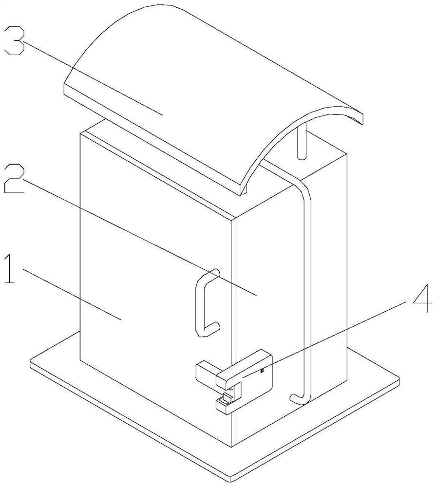
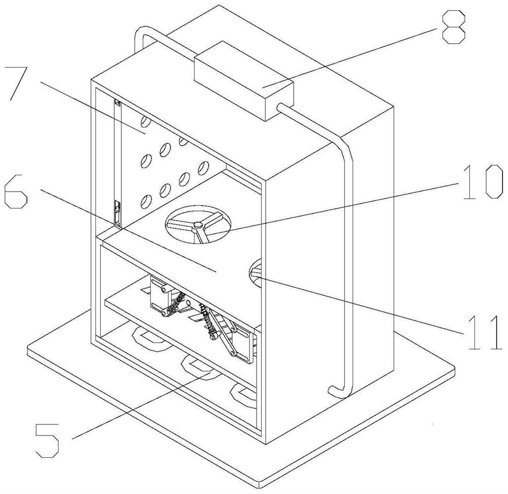
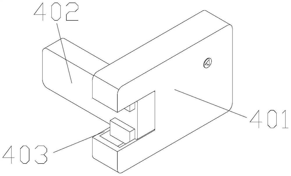
[0031] Attached below Figure 1-8 , clearly and completely describe the technical solutions in the embodiments of the present invention. Obviously, the described embodiments are only a part of the embodiments of the present invention, rather than all the embodiments. Based on the embodiments of the present invention, all other embodiments obtained by those of ordinary skill in the art without creative efforts shall fall within the protection scope of the present invention.

[0032] In the description of the present invention, it should be understood that the terms "portrait", "horizontal", "upper", "lower", "front", "rear", "left", "right", "vertical", The orientation or positional relationship indicated by "horizontal", "top", "bottom", "inner", "outer", etc. is based on the orientation or positional relationship shown in the drawings, and is only for the convenience of describing the present invention, rather than indicating or It is implied that the device or element refer...


PUM


Abstract

The invention discloses a power equipment cooling device which comprises a cabinet body and a cabinet door, the cabinet door is rotatably mounted on the cabinet body, a locking assembly is mounted on the cabinet body and matched with the cabinet door, a cooling box is arranged in the cabinet body, a condensation pipe is mounted in the cooling box, a condenser is arranged at the top of the cabinet body, and a cooling fan is arranged in the condenser. One end of the condensation pipe is installed at the output end of the condenser, the other end of the condensation pipe is installed at the input end of the condensation pipe, and an exhaust fan and an air blower are installed at the top of the cooling box. Heat emitted by the power equipment is mixed with gas in the cooling box under the action of the exhaust fan and the blower, so that the temperature of the space where the power equipment is located is reduced, the aging speed of cables and electronic components in the power equipment is greatly reduced, and the service life of the power equipment is prolonged.

Description

technical field [0001] The invention belongs to the technical field of power equipment cooling, and particularly relates to a power equipment cooling device. Background technique [0002] Power equipment mainly includes two categories: power generation equipment and power supply equipment. Power generation equipment is mainly power station boilers, steam turbines, gas turbines, hydraulic turbines, generators, transformers, etc. In daily life, we are more common power equipment such as transformers or mutual inductors, people usually set protective casings for them to avoid accidents, but because of the casing, the power equipment will be in a relatively closed space In this way, the heat generated by the power equipment during operation cannot be dissipated in time, which accelerates the aging speed of cables and electronic components, and greatly reduces the service life of the power equipment. SUMMARY OF THE INVENTION [0003] The purpose of the present invention is to ...

Claims


Application Information

Patent Timeline
Patent Type & Authority Applications(China)
IPC IPC(8): H05K7/20H05K5/02B01D53/26H02B1/56H02B1/28H02B1/54H02B1/30H02B1/32
CPCH05K7/20136H05K7/20318H05K5/0217B01D53/263H02B1/565H02B1/28H02B1/54H02B1/30H02B1/32
Inventor 王浩辛卫环杨晓红侯振凯邢爱博董慧田忠禹杨全恒李小冉
Owner STATE GRID SHANDONG ELECTRIC POWER CO PINGYUAN POWER SUPPLY CO
Why Eureka
Try Eureka