
Electromagnetic induction heat compensation device and method for ultra-large H-shaped steel rolling process

A rolling process, H-beam technology, applied in the field of steel manufacturing, to achieve the effects of rapid heating in a short time, suppression of wave phenomenon, and multi-temperature compensation

Pending Publication Date: 2022-08-02
TAIYUAN UNIV OF TECH
View PDF12 Cites 0 Cited by
  • Summary
  • Abstract
  • Description
  • Claims
  • Application Information

AI Technical Summary

Problems solved by technology

At present, there is no supplementary heating device suitable for super-large H-shaped steel in the rolling process in industrial production

Method used


Image

  • Electromagnetic induction heat compensation device and method for ultra-large H-shaped steel rolling process
  • Electromagnetic induction heat compensation device and method for ultra-large H-shaped steel rolling process
  • Electromagnetic induction heat compensation device and method for ultra-large H-shaped steel rolling process

Examples


Embodiment 1

[0049] Example 1: Electromagnetic induction heating device for super-large H-beam rolling process

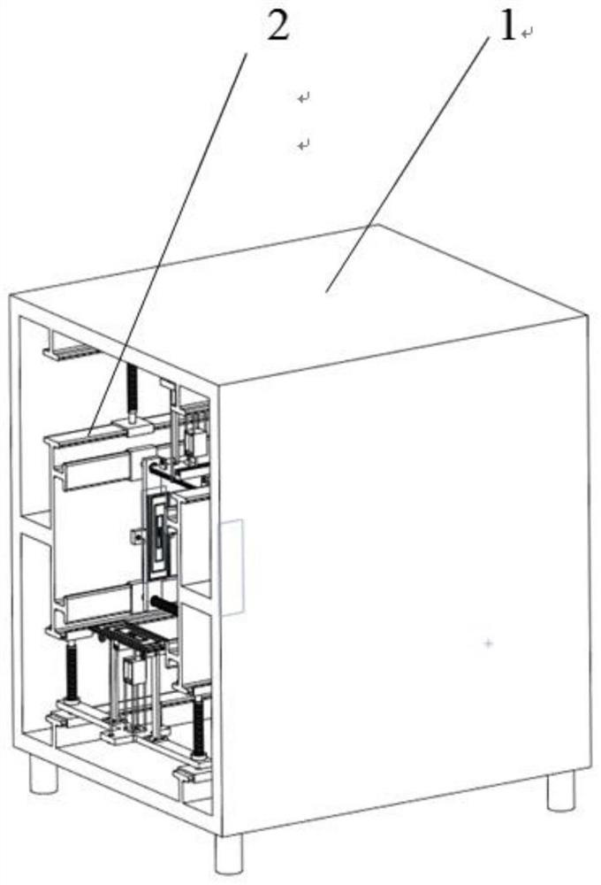
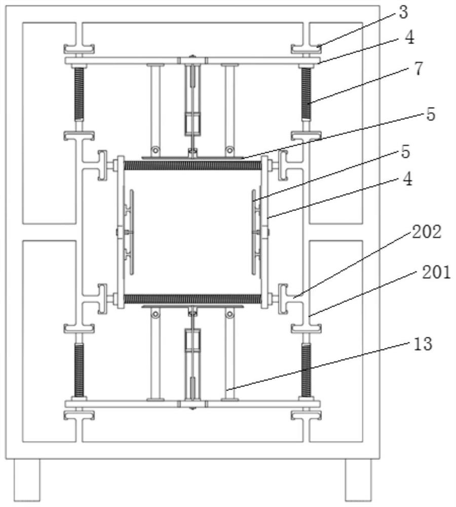
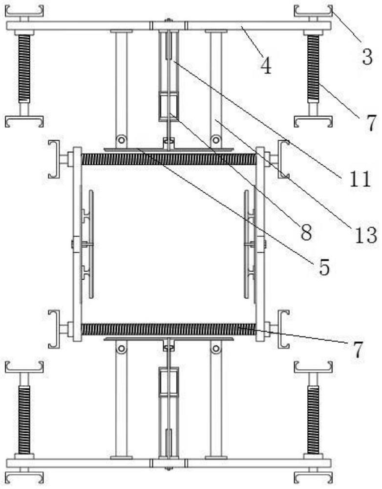
[0050] The embodiment of the present invention provides an electromagnetic induction heating device used in the rolling process of super-large H-beam, such as Figure 1 to Figure 7 As shown in the figure, the device includes a load-bearing bracket 1, a slide rail 2 and a control unit (not shown in the figure). The adjustment mechanism includes a slider 3, a support plate 4, a heat shield 5, a coil 6, a lead screw 7, a drive unit, a temperature sensor 9 and a distance sensor 10. The slider 3 is arranged on the slide rail 2, and the The slider 3 is connected to the support plate 4 , the heat insulation plate 5 is installed on the support plate 4 , the coil 6 is installed on the heat insulation plate 5 , the temperature sensor 9 and the temperature sensor 9 are installed on the support plate 4 . The distance sensor 10 and the temperature sensor 9 are used to detect the temperature...

Embodiment 2

[0065] Example 2: Electromagnetic induction heating method for super large H-beam rolling process

[0066] Figure 8 Shown is a flow chart of an electromagnetic induction heating method for super-large H-beam rolling process according to an embodiment of the present invention. The embodiment of the present invention discloses an electromagnetic induction heating method for super-large H-beam rolling process. The method is implemented based on the device described in Embodiment 1, as shown in Figure 8 As shown, the method includes:

[0067] Step S101, based on finite element simulation, obtain the initial temperature distribution of the H-beam under different initial sizes;

[0068] Step S102, constructing a temperature difference distribution curve based on the lowest point temperature value;

[0069] Step S103, initialize the coil deflection w and the power P;

[0070] Step S104, adjusting the safety distance S between the lowest point of the coil and the H-beam;

[007...


PUM


Abstract

The invention discloses an electromagnetic induction heat compensation device and method used in the ultra-large H-shaped steel rolling process, the device comprises a bearing support, a sliding rail and a control unit, the sliding rail is arranged in the bearing support, an adjusting mechanism is arranged on the sliding rail, and the adjusting mechanism comprises a sliding block, a supporting plate, a heat insulation plate, a coil, a lead screw, a driving unit, a temperature sensor and a distance sensor. The sliding block is arranged on the sliding rail, the sliding block is connected with the supporting plate, the heat insulation plate is installed on the supporting plate, the coil is arranged on the heat insulation plate, the temperature sensor and the distance sensor are arranged on the supporting plate, the lead screw is coaxially connected with the sliding block, the output end of the driving unit is connected with the lead screw, and the lead screw is driven by the driving unit to rotate so that the sliding block can move on the sliding rail; the control unit is electrically connected with the temperature sensor, the distance sensor, the coil and the driving unit. The problem of temperature drop in the H-shaped steel rolling process can be effectively solved, the temperatures of the waist and the legs of the H-shaped steel are kept uniform, the elongation tends to be consistent, and the wave defect caused by temperature difference is avoided.

Description

technical field [0001] The invention relates to the technical field of iron and steel manufacturing, in particular to an electromagnetic induction heating device and method used in the rolling process of super-large H-section steel. Background technique [0002] Since the waist thickness of the steel section is inconsistent with the leg thickness (that is, the thickness of the web and flange), the temperature distribution is very uneven due to factors such as heat exchange between itself and the external environment during the rolling process. In the general rolling process, after the H-beam is heated as a whole, since the waist of the H-beam is thinner than the legs, the waist is cooled first during the cooling process, especially at the center of the waist, while the edge part is cooled slowly. Due to the existence of temperature difference, the fluidity of flange and waist metal is inconsistent, resulting in a significant difference in elongation between the two. In sever...

Claims


Application Information

Patent Timeline
Patent Type & Authority Applications(China)
IPC IPC(8): B21B45/00B21B37/74B21B38/00
CPCB21B45/004B21B37/74B21B38/006B21B38/00Y02P10/25
Inventor 任忠凯程前刘晓郭雄伟陈鹏冯浩王涛王志华
Owner TAIYUAN UNIV OF TECH
Learn More