Optical system, image capturing module and terminal
An optical system and near optical axis technology, applied in optics, optical components, instruments, etc., can solve problems such as image distortion, reduced user experience, increased aberration, etc., to correct aberrations, improve imaging quality, and correct chromatic aberrations Effect
- Summary
- Abstract
- Description
- Claims
- Application Information
AI Technical Summary
Problems solved by technology
Method used
Image

Examples
Embodiment 1
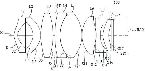
[0089] For a schematic structural diagram of the optical system 100 in this embodiment, see figure 1 As shown, the optical system 100 includes a first lens L1, a second lens L2, a third lens L3, a fourth lens L4, a fifth lens L5, a sixth lens L6, a second lens L2, a third lens L3, a fourth lens L4, a fifth lens L5, a sixth lens L6, The seventh lens L7, the eighth lens L8 and the filter L9, the diaphragm ST is located between the image side S6 of the third lens L3 and the object side S7 of the fourth lens L4, and the imaging surface IMG of the optical system 100 is located in the filter The sheet L9 is away from the side of the eighth lens L8. The materials of the first lens L1, the second lens L2, the sixth lens L6, the seventh lens L7 and the eighth lens L8 are all plastics; the materials of the third lens L3, the fourth lens L4 and the fifth lens L5 are all glass, The filter L9 is an infrared cut-off filter made of glass.
[0090]The first lens L1 has a negative refractive...
Embodiment 2
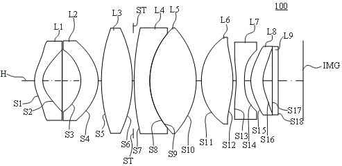
[0107] For a schematic structural diagram of the optical system 100 in this embodiment, see image 3 As shown, the optical system 100 includes a first lens L1, a second lens L2, a third lens L3, a fourth lens L4, a fifth lens L5, a sixth lens L6, a second lens L2, a third lens L3, a fourth lens L4, a fifth lens L5, a sixth lens L6, The seventh lens L7, the eighth lens L8 and the filter L9, the diaphragm ST is located between the image side S6 of the third lens L3 and the object side S7 of the fourth lens L4, and the imaging surface IMG of the optical system 100 is located in the filter The sheet L9 is away from the side of the eighth lens L8. The materials of the first lens L1, the second lens L2, the sixth lens L6, the seventh lens L7 and the eighth lens L8 are all plastics; the materials of the third lens L3, the fourth lens L4 and the fifth lens L5 are all glass, The filter L9 is an infrared cut-off filter made of glass.
[0108] The first lens L1 has a negative refractiv...
Embodiment 3
[0121] For a schematic structural diagram of the optical system 100 in this embodiment, see Figure 5 As shown, the optical system 100 includes a first lens L1, a second lens L2, a third lens L3, a fourth lens L4, a fifth lens L5, a sixth lens L6, a second lens L2, a third lens L3, a fourth lens L4, a fifth lens L5, a sixth lens L6, The seventh lens L7, the eighth lens L8 and the filter L9, the diaphragm ST is located between the image side S6 of the third lens L3 and the object side S7 of the fourth lens L4, and the imaging surface IMG of the optical system 100 is located in the filter The sheet L9 is away from the side of the eighth lens L8. The materials of the first lens L1, the second lens L2, the sixth lens L6, the seventh lens L7 and the eighth lens L8 are all plastics; the materials of the third lens L3, the fourth lens L4 and the fifth lens L5 are all glass, The filter L9 is an infrared cut-off filter made of glass.
[0122] The first lens L1 has a negative refracti...
PUM
 Abstract
Description
Claims
Application Information