
Electrically-controlled light spot shaping and power adjusting device, system and method based on diaphragm

A power adjustment system and power adjustment technology are applied in the fields of optics, optical components, and photometry using electric radiation detectors. It can solve the problems of increased cost, limited application, and continuous adjustment of the diaphragm, and achieves easy Realize and prepare the effect of simple device structure

Active Publication Date: 2022-08-02
YANSHAN UNIV
View PDF12 Cites 0 Cited by
  • Summary
  • Abstract
  • Description
  • Claims
  • Application Information

AI Technical Summary

Problems solved by technology

[0003] At present, the mainstream diaphragms on the market are regular-shaped diaphragms. Generally, some fixed-shaped light holes of different sizes, such as circles and rectangles, are processed on an opaque base plate. The light hole is used with the shading sheet, and the shading sheet is generally of some regular shape, which is suitable for adjusting the light spot with regular optical power distribution, and it is all adjusted for the power of the light spot as a whole. This kind of aperture cannot be continuously adjusted. The application places are relatively limited. These apertures are usually designed for a certain type of product. When processing different products, it is often necessary to redesign the size and shape of the light-transmitting aperture, which increases the cost.
Moreover, for spots with irregular and chaotic optical power distribution, traditional diaphragms combined with shading sheets cannot obtain a spot with consistent optical power distribution, which limits the application and is not flexible enough.

Method used


Image

  • Electrically-controlled light spot shaping and power adjusting device, system and method based on diaphragm
  • Electrically-controlled light spot shaping and power adjusting device, system and method based on diaphragm
  • Electrically-controlled light spot shaping and power adjusting device, system and method based on diaphragm

Examples


Embodiment 1

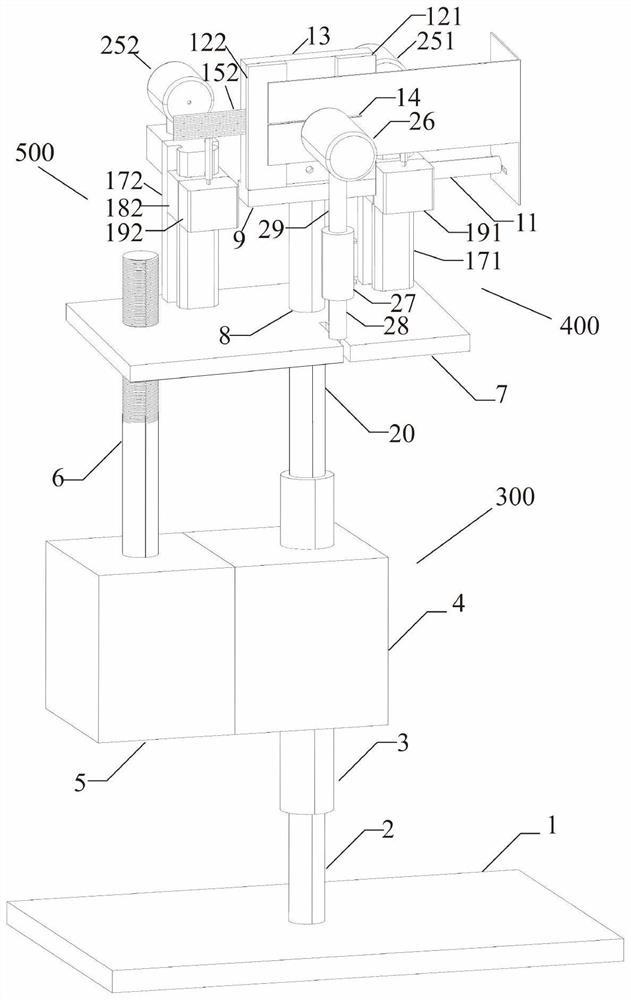
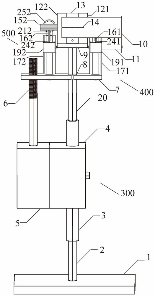
[0070] like Figure 9 Shown is the application of a diaphragm-based electronically controlled spot shaping and power adjustment device and method in the manufacture of optical fiber devices. When multiple fiber gratings are prepared at the same time, multiple fibers are distributed along the Y-axis direction, and the X-axis is required. The spot power corresponding to each optical fiber in the direction is equal, otherwise, the reflectivity of each fiber grating will be inconsistent when prepared at the same time. Due to the irregular distribution of the spot power, the adjustment difficulty is increased. The 2G152 divides the light spot into multiple thin strip-shaped light spots, and adjusts the optical power of the thin-striped light spots in turn, and finally achieves the same optical power of the entire light spot, so that the power of each optical fiber corresponding to the light spot is equal, and the fiber grating with the same reflectivity is prepared.

[0071] The li...

Embodiment 2

[0081] like Figure 10 As shown, the light spot before adjustment is a trapezoidal light spot. If you want to get a rectangular light spot, adjust the thin cylindrical component 1151 and thin cylindrical component 2G152 to form a rectangular aperture, and the trapezoidal light spot passes through the light hole and the thin cylindrical component. The aperture will get a rectangular light spot, which includes the following steps:

[0082] 1. Adjust the height of the transmission mechanism 1Y300 so that the movable displacement of the transmission mechanism 1Y300 covers the position of each thin cylinder of the thin cylinder assembly 1151.

[0083] 2. Adjust the height of the transmission mechanism 2Y400 so that the height of the transmission wheel 1W231 is consistent with the height of the first thin cylinder corresponding to the light spot, and use the electron microscope 1K251 to observe the degree of fit between the transmission wheel 1W231 and the first thin cylinder corres...

Embodiment 3

[0087] like Figure 11 As shown, adjusting the trapezoidal light spot into an elliptical light spot includes the following steps:

[0088] 1. Adjust the height of the transmission mechanism 1Y300 so that the movable displacement of the transmission mechanism 1Y300 covers the position of each thin cylinder of the thin cylinder assembly 1151.

[0089] 2. Adjust the height of the transmission mechanism 2Y400 so that the height of the transmission wheel 1W231 is consistent with the height of the first thin cylinder corresponding to the light spot, and use the electron microscope 1K251 to observe the degree of fit between the transmission wheel 1W231 and the first thin cylinder corresponding to the light spot, as The initial position of the drive wheel 1W231.

[0090] 3. In the same way, adjust the height of the transmission mechanism 3Y500 so that the height of the transmission wheel 2W232 is consistent with the height of the first thin cylinder corresponding to the light spot, a...


PUM


Abstract

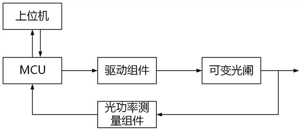
The invention discloses an electrically-controlled light spot shaping and power adjusting device, system and method based on a diaphragm, and belongs to the field of variable diaphragms and light spot shaping and power adjusting. The optical power measuring assembly is used for converting an optical signal into an electric signal; the microcontroller unit is used for calculating data of the optical power measuring assembly, communicating with an upper computer and sending a signal to the driving assembly to control the variable diaphragm assembly; the upper computer is used for receiving, storing and displaying an optical power set value of a thin strip-shaped light spot, displaying a strip-shaped light spot power actual measurement value corresponding to a thin cylinder matched with the transmission wheel, displaying a matching state of the transmission wheel and the thin cylinder, receiving and displaying stepping displacements set for a motor 1D, a motor 2D and a motor 3D and issuing the stepping displacements to the micro-control unit; the variable diaphragm assembly is used for shaping the light spots and adjusting the power of the light spots; the device is simple in structure, easy to implement, capable of measuring adjusted light spots in real time, accurate and convenient.

Description

technical field [0001] The invention belongs to the technical field of variable aperture, light spot shaping and power adjustment, and in particular relates to a diaphragm-based electronically controlled light spot shaping and power adjustment device, system and method. Background technique [0002] In the fields of precision laser micro-processing such as semiconductor devices, photomask manufacturing, and laser writing, it is often necessary to shape and adjust the power of the beam shape of the laser beam, so that the projected or imaged beam presents the required geometric shapes such as circle, Rectangle, etc. or require uniform or regular light power distribution, the device used for light spot shaping is usually a diaphragm. [0003] At present, the mainstream apertures on the market are regular-shaped apertures. Generally, some fixed-shaped apertures of different sizes, such as circles and rectangles, are processed on an opaque base plate. The light hole is used wit...

Claims


Application Information

Patent Timeline
Patent Type & Authority Applications(China)
IPC IPC(8): G02B27/09G02B26/02G02B5/00G01J1/42
CPCG02B27/0927G02B27/0988G02B26/02G02B5/005G01J1/42
Inventor 齐跃峰王玉琳刘长鑫刘雪强高玉金郭星辰
Owner YANSHAN UNIV
Learn More