Cable with efficient cooling function

A function and cable technology, applied in the field of cables with efficient cooling function, can solve problems such as cable damage, improve heat absorption and heat dissipation, improve mixing effect, and ensure the effect of cleanliness

Inactive Publication Date: 2022-08-02
朱庆添
View PDF0 Cites 0 Cited by
  • Summary
  • Abstract
  • Description
  • Claims
  • Application Information

AI Technical Summary

Problems solved by technology

[0004] The purpose of the present invention is to solve the shortcomings in the prior art, and propose a cable with high-efficiency cooling function. The cable uses the cooling liquid to absorb the heat generated by the cable, and then utilizes the flow of the cooling liquid in the serpentine tube The heat is quickly discharged to the outside, so as to avoid the damage of the cable caused by the high temperature inside the cable. At the same time, the disturbance of the cooling liquid by the stirring rod and the shaking of the floating ball in the cooling liquid can further make the cooling liquid absorb heat evenly. Improve the effect of heat absorption

Method used


Image

  • Cable with efficient cooling function
  • Cable with efficient cooling function
  • Cable with efficient cooling function

Examples


Embodiment 1

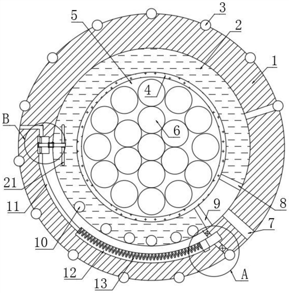
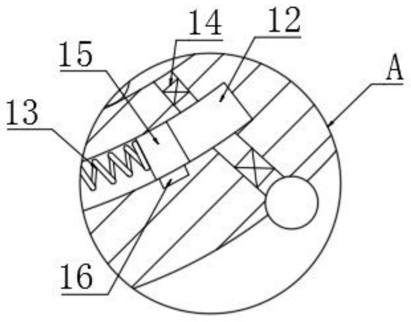
[0025] refer to Figure 1-3 , a cable with high-efficiency cooling function, comprising a casing 1, a liquid storage cavity 2 is arranged in the casing 1, an installation cavity 5 in the casing 1, a plurality of cables 6 are installed in the installation cavity 5, and the liquid storage cavity 2 The inner wall of the casing is provided with a heat-conducting plate 4, the inner side of the heat-conducting plate 4 extends into the installation cavity 5, the liquid storage cavity 2 is filled with cooling liquid, the housing 1 is provided with a reciprocating cavity 12, and the reciprocating cavity 12 is provided with a reciprocating mechanism, The reciprocating mechanism includes a moving block 15 arranged in the reciprocating cavity 12. The moving block 15 is slidably connected to the inner wall of the reciprocating cavity 12. The left side of the moving block 15 is elastically connected to the left inner wall of the reciprocating cavity 12 through an electrified spring 13, and t...

Embodiment 2

[0037] refer to Figure 4-5 The difference between this embodiment and Embodiment 1 is that the outer side of the housing 1 is provided with a mounting block 23, the upper end of the mounting block 23 is fixedly connected with an arc-shaped airbag 25, and the outer side of the housing 1 is provided with a chute 26 to slide the A sliding block 27 is slidably connected in the groove 26, the left side of the sliding block 27 extends to the outside world, the side of the arc-shaped airbag 25 away from the mounting block 23 is fixedly connected with the lower end of the sliding block 27, and the left space of the reciprocating cavity 12 passes through the outside world. The air intake pipe 22 is communicated, and the air outlet end of the exhaust pipe 17 is communicated with the arc-shaped air bag 25. The arc-shaped air bag 25 has self-recovery properties. The arc-shaped air bag 25 is communicated with the outside through the jet pipe 29. After the solenoid valve of the air pipe 29...


PUM


Abstract

A cable with an efficient cooling function disclosed by the present invention comprises a shell, a liquid storage cavity is arranged in the shell, the liquid storage cavity is filled with a cooling liquid, a reciprocating cavity is arranged in the shell, a reciprocating mechanism is arranged in the reciprocating cavity, the reciprocating mechanism comprises a moving block arranged in the reciprocating cavity, and the moving block is connected with the reciprocating cavity. The moving block is slidably connected with the inner wall of the reciprocating cavity, the left side of the moving block is elastically connected with the inner wall of the left side of the reciprocating cavity through an electrified spring, the moving block has conductivity, and a conducting strip is arranged at the inner bottom of the reciprocating cavity. According to the cable, cooling liquid is used for absorbing heat generated by the cable, then the cooling liquid flows in the coiled pipe to quickly discharge the heat to the outside, so that the situation that the cable is damaged due to the fact that the temperature in the cable is too high is avoided, meanwhile, the stirring rod disturbs the cooling liquid, and the floating ball shakes in the cooling liquid; and the cooling liquid can further uniformly absorb heat, and the heat absorption effect is improved.

Description

technical field [0001] The invention relates to the technical field of cables, in particular to a cable with a high-efficiency cooling function. Background technique [0002] A cable is a power or signal transmission device, usually composed of several or several groups of wires. With the continuous improvement of living standards, it also further promotes the continuous development of the power industry. In the current power industry, cables are essential. It is one of the few power transmission equipment, so that it can use cables to transmit electric energy thousands of miles away to thousands of households. However, the existing cables still have the following problems: [0003] In the high temperature environment in summer, the outside temperature is high. At the same time, due to the increase in the use of air conditioners in summer, the load of the cable inside the cable continues to increase, resulting in a continuous increase in the heat generated on the cable. Due ...

Claims


Application Information

Patent Timeline
Patent Type & Authority Applications(China)
IPC IPC(8): H01B7/42H01B7/00B08B5/02
CPCH01B7/425H01B7/428H01B7/00B08B5/02Y02A30/14
Inventor 朱庆添
Owner 朱庆添
Why Eureka
Try Eureka