Heating coordination mechanism for efficient dust removal

A high-efficiency, dust-removing box technology, applied in the direction of electrostatic effect separation, cleaning methods and appliances, cleaning methods using tools, etc., can solve the problems of insufficient gas contact area, insufficient gas heating effect, and reduced post-stage dust removal effect, etc., to achieve Reduces pressure, guarantees anti-corrosion protection effect, reduces impact effect

Pending Publication Date: 2022-08-05
HUANENG QUFU THERMAL POWER CO LTD
View PDF0 Cites 0 Cited by
  • Summary
  • Abstract
  • Description
  • Claims
  • Application Information

AI Technical Summary

Problems solved by technology

[0003] Before performing electrostatic dust removal work on the gas in the thermal power plant, the gas in the pipeline needs to be heated to remove the moisture in the gas in the pipeline. Since the gas contains acidic substances, the humid gas attached to the inside of the device will easily lead to corrosion of the device, and the traditional The ceramic sleeve heating device does not have a large contact area with the gas during heating, and the gas flow rate is too fast, which will lead to insufficient gas heating effect, resulting in moisture in the air flow, reducing the dust removal effect in the later stage

Method used


Image

  • Heating coordination mechanism for efficient dust removal
  • Heating coordination mechanism for efficient dust removal
  • Heating coordination mechanism for efficient dust removal

Examples


Embodiment Construction

[0027] The technical solutions in the embodiments of the present invention will be clearly and completely described below with reference to the accompanying drawings in the embodiments of the present invention. Obviously, the described embodiments are only a part of the embodiments of the present invention, rather than all the embodiments.

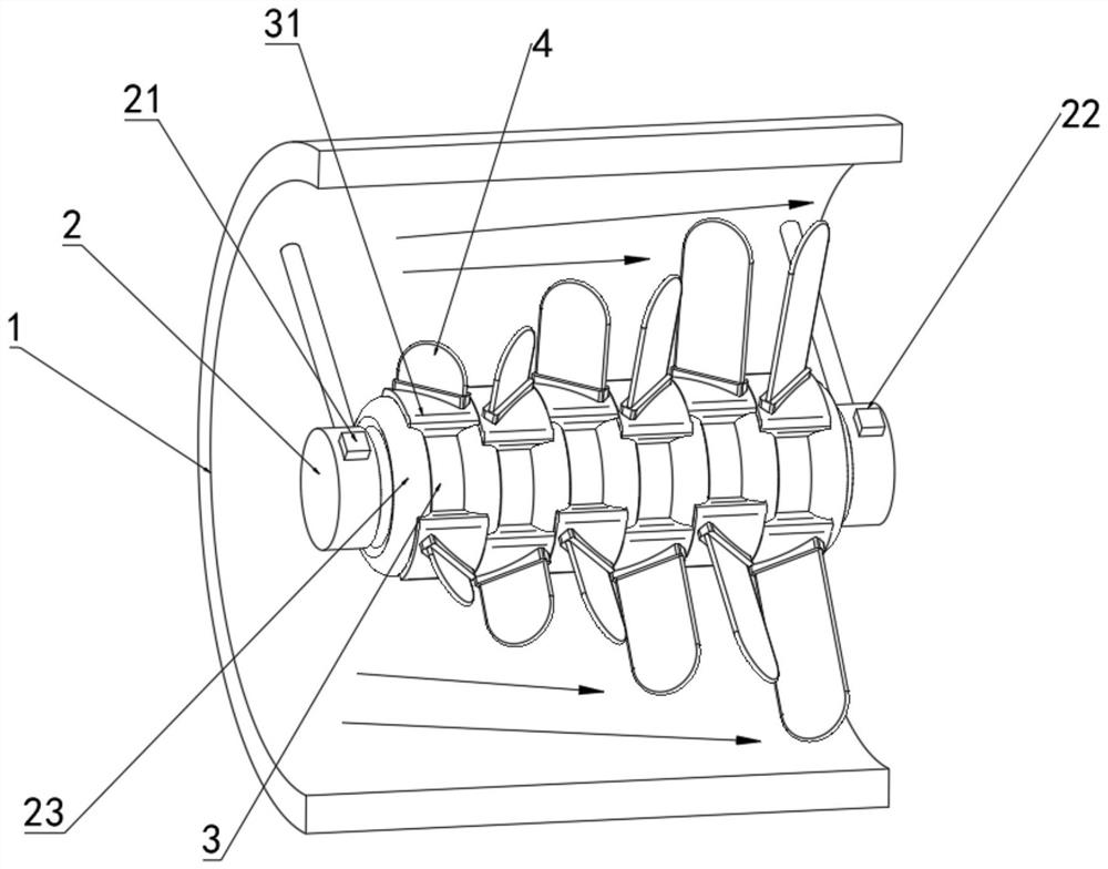
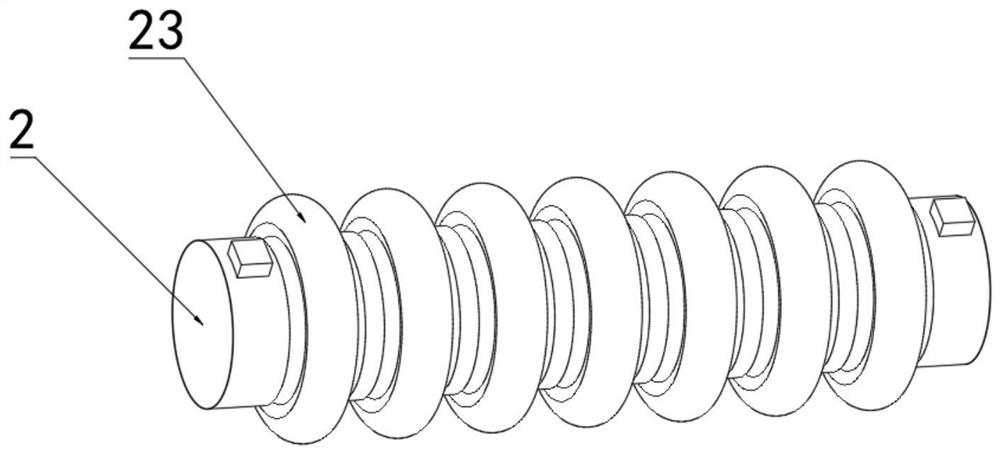
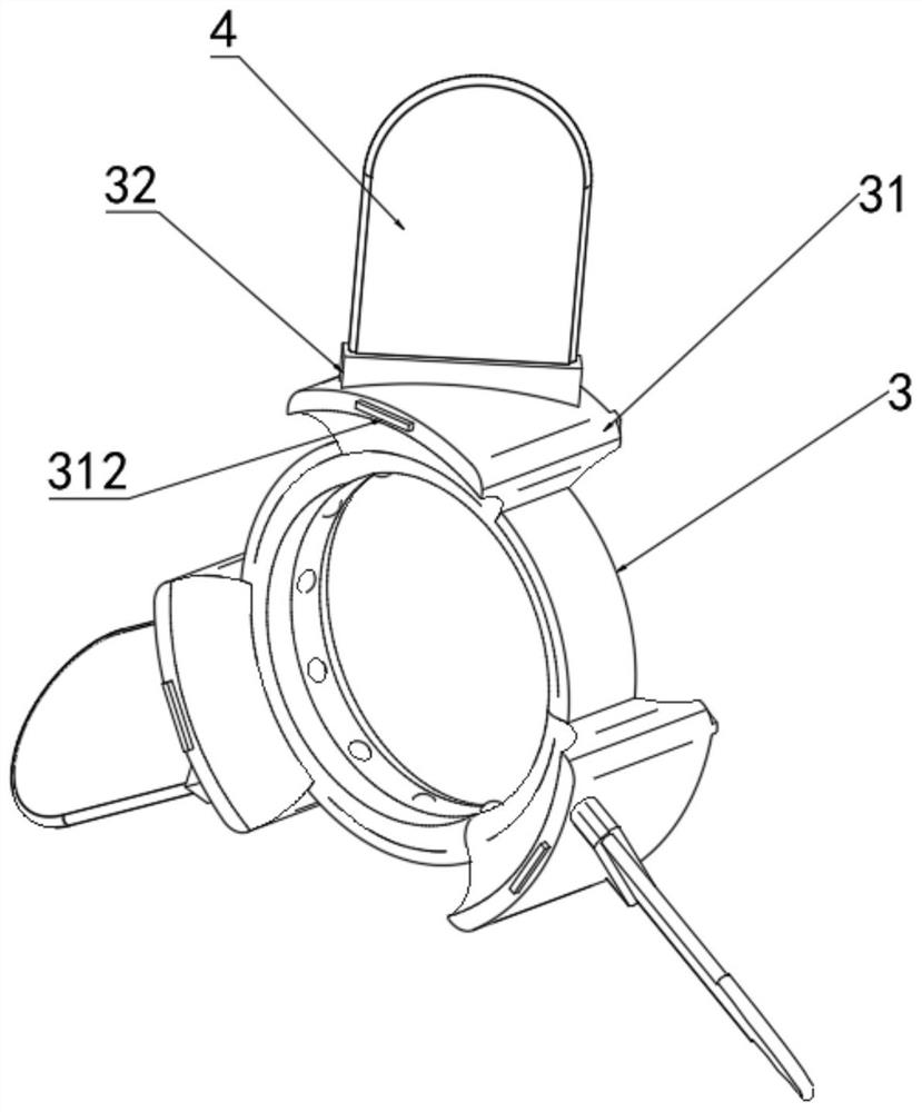
[0028] refer to Figure 1-8 , a heating coordination mechanism for high-efficiency dust removal, including a flue gas flow channel 1, an electric heater 2 is fixedly installed at the inner center of the flue gas flow channel 1 through a plurality of sets of fixed shafts, and the outer fixed sleeve of the electric heater 2 is connected with a ring-shaped Porcelain sleeve 23, the outer side wall of the electric heater 2 is located at both ends of the annular porcelain sleeve 23, and a first temperature measuring device 21 and a second temperature measuring device 22 are respectively fixedly installed. A sliding ring 3 is provided. The outer ...


PUM


Abstract

The invention discloses a heating coordination mechanism for efficient dust removal, and relates to the technical field of electrostatic dust removal heating, the heating coordination mechanism comprises a flue gas flow channel, an electric heater is fixedly mounted at the center of the interior of the flue gas flow channel through a plurality of groups of fixing shafts, and an annular porcelain sleeve fixedly sleeves the exterior of the electric heater; a first temperature detector and a second temperature detector are fixedly installed at the positions, located at the two ends of the annular porcelain bushings, of the outer side wall of the electric heater correspondingly, and a sliding ring is arranged between every two adjacent annular porcelain bushings. According to the electric heater, when airflow passes through the electric heater, the flow rate of the airflow can be reduced through the design of the multiple sets of driving blades, meanwhile, heat generated by the annular porcelain sleeve can be dissipated through rotation of the sliding ring and the driving blades, the contact area of the heating mechanism and the airflow is greatly increased, and the contact area of the heating device and the airflow is remarkably increased; the heating efficiency of the electric heater on the airflow is higher, and the efficient proceeding of subsequent dust removal work is ensured.

Description

technical field [0001] The invention relates to the technical field of electrostatic dust removal and heating, in particular to a heating coordination mechanism for high-efficiency dust removal. Background technique [0002] Electrostatic precipitation is a kind of gas dust removal method; dust-containing gas is electrically separated when it passes through a high-voltage electrostatic field. After the dust particles and negative ions are combined with negative charges, they tend to discharge and deposit on the surface of the anode; it is used in metallurgy, chemical and other industries to purify gas Or recover useful dust particles; use electrostatic field to ionize gas so that dust particles are charged and adsorbed on the electrode; air molecules are ionized into positive ions and electrons in a strong electric field, and electrons encounter dust particles in the process of running to the positive electrode , so that the dust particles are negatively charged to the posit...

Claims


Application Information

Patent Timeline
Patent Type & Authority Applications(China)
IPC IPC(8): B03C3/014B03C3/017B03C3/34B08B1/00B08B1/02B08B1/04
CPCB03C3/014B03C3/017B03C3/34B08B1/005B08B1/02B08B1/04Y02A50/2351
Inventor 张建军朱怀超张心逸李涛孙同晋徐兴革马俊喜李宁张海强张海宾张爱霞
Owner HUANENG QUFU THERMAL POWER CO LTD
Why Eureka
Try Eureka