
Swinging self-adaptive adjustment type spindle-free rotary cutter and working method thereof

A technology of self-adaptive adjustment and rotary cutting machine, which is applied in the direction of circular rotary machines, manufacturing tools, wood processing appliances, etc., can solve the problems of low wood output rate and inability to adjust according to actual conditions, and achieve good quality of round logs , Reasonable design, simple operation

Active Publication Date: 2022-08-05
福州三木三森机械有限公司
View PDF11 Cites 0 Cited by
  • Summary
  • Abstract
  • Description
  • Claims
  • Application Information

AI Technical Summary

Problems solved by technology

[0002] At present, the production of plywood veneer equipment in our country is completed by a rotary cutter with a card shaft and a rotary cutter without a card shaft. The working principle of the rotary cutter without a card shaft is that three driving rollers clamp the wood and drive the wood in two sets of driving rollers. Rotate, the double driving rollers drive the wood while moving toward the blade direction to extrude the wood (moving toward the single driving roller direction). The blade removes the branches, scars and skin on the surface of the wood, and processes the irregular logs into the required round logs. However, in the process of collecting materials, you will definitely encounter all kinds of wood, such as bark, curved, oval, large and small, S-shaped, and scarred branches, etc., which need to be removed first. , leaving the usable ones for secondary processing, but the existing cardless rotary cutting machines are all rigid and directly perform rotary cutting on round logs, which cannot be adjusted according to the actual situation, so that the processed wood will be removed more Outer skin, resulting in low yield of wood

Method used


Image

  • Swinging self-adaptive adjustment type spindle-free rotary cutter and working method thereof
  • Swinging self-adaptive adjustment type spindle-free rotary cutter and working method thereof
  • Swinging self-adaptive adjustment type spindle-free rotary cutter and working method thereof

Examples


Embodiment Construction

[0021] The present invention will be further described below with reference to the accompanying drawings and embodiments.

[0022] It should be noted that the following detailed description is exemplary and intended to provide further explanation of the present application. Unless otherwise defined, all technical and scientific terms used herein have the same meaning as commonly understood by one of ordinary skill in the art to which this application belongs.

[0023] It should be noted that the terminology used herein is for the purpose of describing specific embodiments only, and is not intended to limit the exemplary embodiments according to the present application. As used herein, unless the context clearly dictates otherwise, the singular is intended to include the plural as well, furthermore, it is to be understood that when the terms "comprising" and / or "including" are used in this specification, it indicates that There are features, steps, operations, devices, compone...


PUM


Abstract

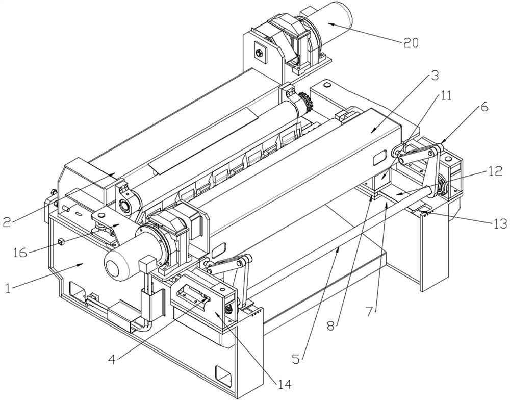
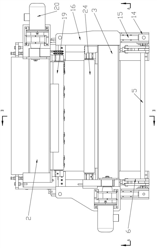
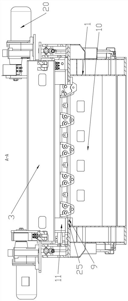
The invention provides a swing self-adaptive adjustment clamping-shaft-free rotary cutter and a working method thereof.The swing self-adaptive adjustment clamping-shaft-free rotary cutter comprises a working table, a fixed beam and a movable beam, the fixed beam is fixedly connected to the working table, and the movable beam is slidably connected to the working table corresponding to the fixed beam. Driving mechanisms used for driving the movable beam to move are installed at the positions, at the two ends of the movable beam, of the workbench, a balance rod is rotationally connected between the two driving mechanisms, and the two ends of the movable beam are connected with the two ends of the balance rod through connecting rod structures. The device is reasonable in design, easy to operate, convenient to use, high in log outturn percentage and good in log quality, specialized production is facilitated, and the production efficiency is improved.

Description

technical field [0001] The invention relates to a non-clamping shaft rotary cutting machine capable of swinging and adaptive adjustment and a working method thereof. Background technique [0002] At present, the production of plywood veneer equipment in my country is completed by a rotary cutting machine with a clamping shaft and a rotary cutting machine without a clamping shaft. The working principle of the rotary cutting machine without a clamping shaft is that three driving rollers clamp the wood and drive the wood in two sets of driving rollers. Rotating, the double drive rollers move towards the blade while driving the wood to squeeze the wood (to move towards the single drive roller). The blade removes the branches, scars and skins on the surface of the wood, and the irregular logs are processed into the required logs. However, in the process of collecting materials, you will encounter all kinds of wood, such as bark, curved, oval, big and small, S-shaped, scarred branch...

Claims


Application Information

Patent Timeline
IPC IPC(8): B27C5/08B27L5/02
CPCB27C5/08B27L5/027
Inventor 李承华丁强张景南
Owner 福州三木三森机械有限公司
Learn More