Supercharge Your Innovation With Domain-Expert AI Agents!

Hydraulic control system for electric control mechanical automatic transmission

A technology of hydraulic control system and automatic transmission, which is applied in transmission device control, fluid pressure actuation system components, mechanical equipment, etc., can solve the problems of slow response speed, difficult mass production, and complicated control, and achieves simple control and reduced size. The effect of hydraulic shock and perfect shift control system

Pending Publication Date: 2022-08-05
CHONGQING TSINGSHAN IND
View PDF0 Cites 1 Cited by
  • Summary
  • Abstract
  • Description
  • Claims
  • Application Information

AI Technical Summary

Problems solved by technology

[0004] ① Electronic control-pneumatic shift control system, although it is easy to improve and low in cost, its performance is poor;
[0005] ② Electronic control-electric shift control system, using stepping motor to control the clutch and shift device, the reaction speed is slow, the debugging is complicated, and it is difficult to mass produce;
[0006] ③ Electronic control-hydraulic shift control system, such as the Selespeed automatic manual transmission control system of Marelli Group, the oil pressure can only be within the range of 45 to 55 bar, and the clutch, gear selection cylinder and shift cylinder are controlled by the hydraulic system, and the / Downshifts can only be carried out sequentially from one gear to the next. For example, if you want to change from the first gear to the third gear, you must push the gear lever forward twice to make the shift drum rotate 2 50°, first go through the second gear and then shift into it. Three gears, complex control, high cost

Method used


Image

  • Hydraulic control system for electric control mechanical automatic transmission

Examples


Embodiment Construction

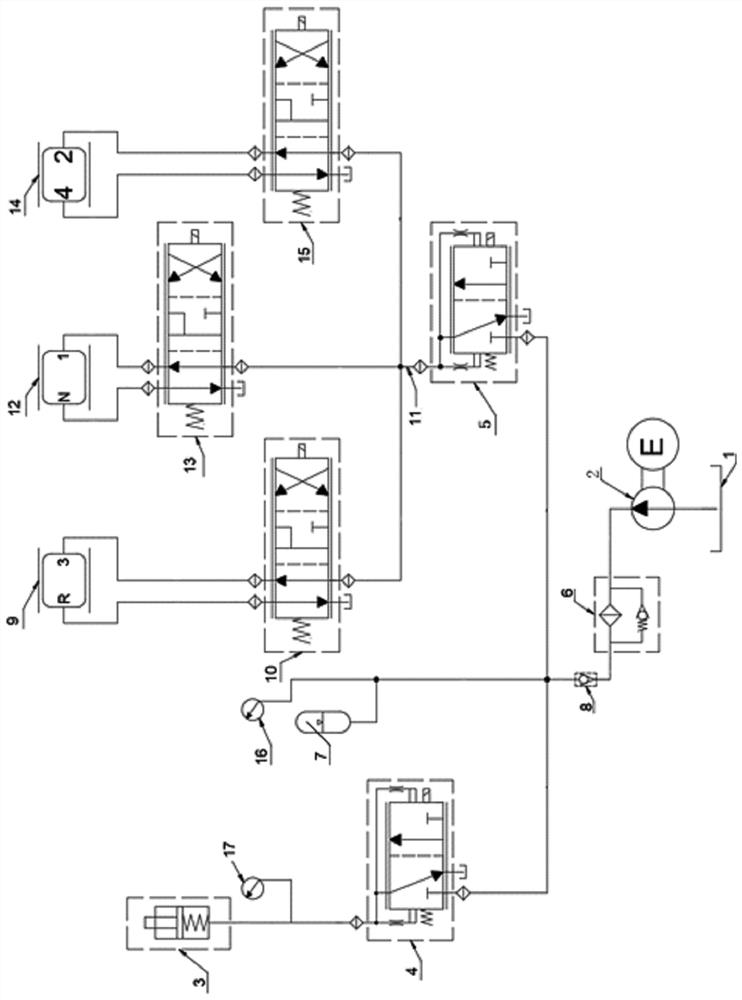
[0028] like figure 1 As shown, a hydraulic control system for an electronically controlled mechanical automatic transmission includes a transmission oil supply unit, a shift control unit, and a clutch control unit. The transmission oil supply unit includes an oil tank 1, an oil pump 2, a main Oil circuit, the main oil circuit is provided with a one-way valve 8, an accumulator 7 is communicated with the main oil circuit through the oil passage, and a first hydraulic sensor 16 is arranged between the accumulator 7 and the main oil circuit. It is used to monitor the real-time oil pressure of the main oil circuit. The oil circuit at the upstream end of the oil pump 2 communicates with the oil tank 1, and the oil circuit at the downstream end of the oil pump 2 communicates with the main oil circuit. In this embodiment, the oil circuit at the downstream end of the oil pump 2 communicates with the main oil circuit through a filter 6. The oil circuit is connected, and the filter 6 is...


PUM


Abstract

A hydraulic control system for an electronic control mechanical automatic transmission comprises a transmission oil supply unit, a gear shifting control unit and a clutch control unit, the transmission oil supply unit comprises an oil tank, an oil pump and a main oil way, an upstream end oil way of the oil pump is communicated with the oil tank, and a downstream end oil way of the oil pump is communicated with the main oil way. The clutch control unit comprises a clutch separation oil cylinder, the clutch separation oil cylinder is communicated with the main oil way through a clutch oil supply control pipeline, and a clutch oil supply control electromagnetic valve is arranged on the clutch oil supply control pipeline and used for controlling separation of a clutch. The gear shifting control unit comprises a gear shifting oil supply electromagnetic valve and a plurality of gear control oil ways, an upstream end oil way of each gear control oil way communicates with an oil outlet hole of the gear shifting oil supply electromagnetic valve, and an oil inlet hole of the gear shifting oil supply electromagnetic valve communicates with the main oil way. Each gear control oil way is composed of a gear shifting oil cylinder and a gear shifting electromagnetic valve which are communicated through an oil duct, and an oil return opening of each electromagnetic valve is communicated with the oil tank.

Description

technical field [0001] The invention relates to the field of AMT hydraulic control, in particular to a hydraulic control system for an electronically controlled mechanical automatic transmission. Background technique [0002] Automated mechanical transmission (AMT) for short A stepped mechanical automatic transmission. [0003] The shift control systems used in the existing AMT are generally divided into three types: [0004] ① The electronic control-pneumatic shift control system, although easy to improve and low cost, has poor performance; [0005] ② The electronic control-electric shift control system adopts stepper motor to control the clutch and shift device, the response speed is slow, the debugging is complicated, and it is difficult to mass produce; [0006] ③ Electronic control-hydraulic shift control system, such as Marelli Group's Selespeed manual transmission control system, the oil pressure can only be in the range of 45 ~ 55bar, through the hydraulic system ...

Claims


Application Information

Patent Timeline
Patent Type & Authority Applications(China)
IPC IPC(8): F16H61/00F15B21/041F15B1/02
CPCF16H61/0009F15B21/041F15B1/021F16H2061/0034
Inventor 文武彭灿周勇包振庆
Owner CHONGQING TSINGSHAN IND
Features
  • R&D
  • Intellectual Property
  • Life Sciences
  • Materials
  • Tech Scout
  • Unparalleled Data Quality
  • Higher Quality Content
  • 60% Fewer Hallucinations
Learn More