Spiral groove gas dynamic pressure bearing test device

A gas dynamic pressure bearing and test device technology, which is applied in mechanical bearing testing, measuring devices, testing of mechanical components, etc., can solve problems such as precise control of rotor speed, unstable speed, and influence on test accuracy

Inactive Publication Date: 2022-08-05
XINYANG VOCATIONAL & TECHN COLLEGE
View PDF3 Cites 0 Cited by
  • Summary
  • Abstract
  • Description
  • Claims
  • Application Information

AI Technical Summary

Problems solved by technology

However, the rotor of this device is driven by a high-pressure gas blowing turbine, but this driving method cannot accura

Method used


Image

  • Spiral groove gas dynamic pressure bearing test device
  • Spiral groove gas dynamic pressure bearing test device
  • Spiral groove gas dynamic pressure bearing test device

Examples


Embodiment 1

[0047] Reference Figure 1-Figure 4 The example of this embodiment is used to provide a spiral groove bearing test device.

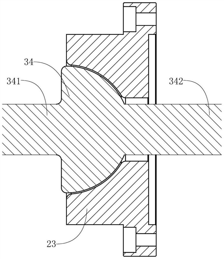
[0048] like figure 1 The section of the spiral groove bearing for the test to be tested is a spherical spiral groove gas dynamic storm bearing, including the stator 23 and the rotor 34. Both have standard spherical sphere. 23 gaps in the stator. A fixed setting of the Rotary 34 Star 23 is set with a driving shaft 341, a fixed setting of the side of the stator 23 with a load shaft 342, and the load shaft 342 runs through the stator 23. Rotor 34, driving shaft 341 and load shaft 342 common axis. Because the spiral grooves of the spiral groove bearing are shallow, therefore figure 1 No display.

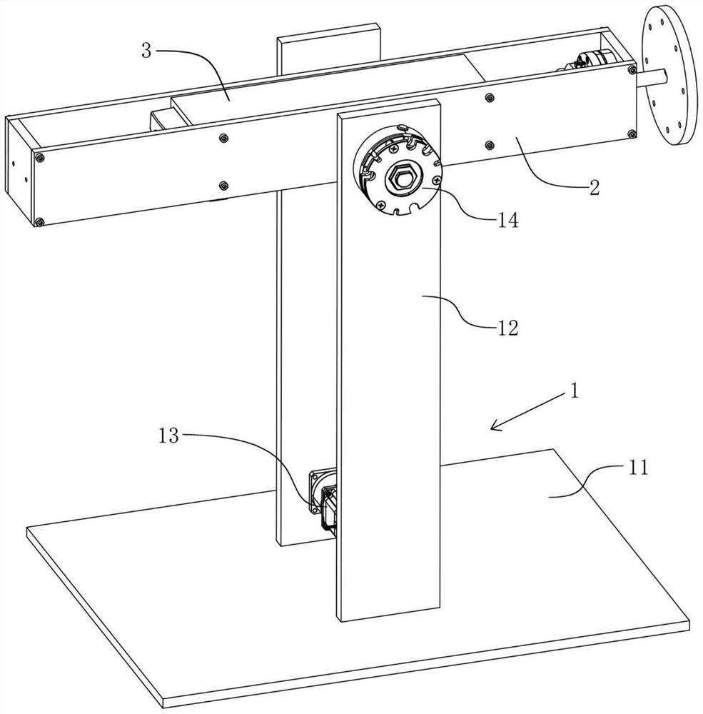
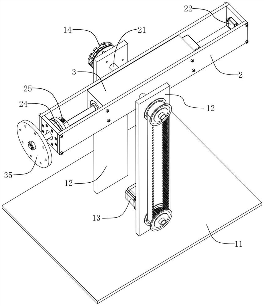
[0049] like figure 2 As well as image 3 The test device includes support base 1, support base 1 to support the invention on the ground or countertop. Support base 1 includes the bottom board 11 and the standing board 12, the bottom board 11 level settings, the standing ...

Embodiment 2

[0069] Reference Figure 5-Figure 7 Compared with the Example 1, the spiral groove bearing test device provided by this embodiment has been improved compared to the embodiment 1: it can also test the spherical spiral gases of the spherical pipe gases with a angle spiral groove of the stator 23 and the rotor 34.

[0070] Compared with the cone spiral groove bearing, the spherical spiral groove bearing is still working properly even between the stator 23 and the rotor 34. The performance in this case also needs to pass test verification. like Figure 5 The sphere of spherical spiral groove bearing of the spherical spiral groove of the embodiment of this embodiment, the stator 23 and the rotor 34 set the settings, both have standard sphere, but the two are in a non -coaxial state with angle, and the rotor 34 34 There is no load shaft 342 on the top.

[0071] like Image 6 The assembly diagram (explosion map) of the rotary bracket 2 and its internal and external components, the bearing b...


PUM


Abstract

The invention provides a spiral groove gas dynamic pressure bearing test device, and belongs to the technical field of spiral groove bearing detection. The spiral groove gas dynamic pressure bearing testing device comprises a spiral groove gas dynamic pressure bearing to be tested, the spiral groove gas dynamic pressure bearing comprises a stator and a rotor which are arranged in a matched mode, and a driving shaft is coaxially arranged on the side, away from the stator, of the rotor; the device further comprises a rack unit, a positioning unit, a driving unit and a control analysis unit, the rack unit comprises a supporting base, a rotating support and a bearing support, the positioning unit is used for controlling the inclination angle of the rotating support, and the driving unit is used for driving the rotor to rotate. The control analysis unit comprises a control mechanism, a torque sensor and a vibration sensor. The friction performance and the stability performance of the spiral groove gas dynamic pressure bearing can be tested and displayed, the gas lubrication characteristic, the dynamic stability and other characteristics of the bearing can be visually displayed to students, and a simulation verification test can also be carried out.

Description

Technical field [0001] The present invention is a spiral groove bearing detection technology, which is specific to a test device suitable for spiral gaseous gas pressure bearing. Background technique [0002] The spiral groove bearing is a fluid lubricant. It has a spiral groove on its stator or rotor. It is often used in high -speed vertical turnover systems, such as an energy storage flywheel system to obtain lower friction power consumption. Among them, the cone spiral groove bearing and the spherical spiral groove can bear the radial load and axial load at the same time. The spiral gaseous dynamic storm bearing is a spiral groove bearing with the air as the lubricant. When the rotor rotates at a high speed, the air between the rotor and the stator will form a gas film under the action of the spiral groove. [0003] On the one hand, in the courses involving the spiral groove bearing, due to the lack of test devices for spiral groove bearings, it is not possible to use the bear...

Claims


Application Information

Patent Timeline
IPC IPC(8): G01M13/04G01M13/045
CPCG01M13/04G01M13/045Y02E60/16
Inventor 张亚平王振宇杨自斌胡荣博李秋爽
Owner XINYANG VOCATIONAL & TECHN COLLEGE
Why Eureka
Try Eureka